3 - 3
3-2 TRANSMITTER CIRCUITS
TX AF CIRCUITS
The TX AF circuit consists of microphone amplifier (MIC
AMP), ALC and AF fi lters. ALC (Automatic Level Control) is
an amplifi er which reduces its gain automatically to prevent
over deviation.
The audio signals from the connected headset's microphone
(MIC signals) are passed through the electric volume to be
adjusted MIC gain, and amplifi ed by ALC (Automatic Level
Control) AMP and MIC AMP. The amplifi ed MIC signals are
passed through the MOD/AF SW and the switched capacitor
filter (IC7) which removes unwanted signals. The filtered AF
signals are passed through the HPF, and amplified by buffer,
then applied to the AM modulation cicuits as the modulation
signals, via the DAC for deviation adjustment.
AF
AMP
HPFLPF
MC1/2
ALC
AMP
BUFF
SW
MOD/AF
IC26
IC2 IC13 IC22 IC8
DAC
IC78
IC7
IC9
AM_DEPTH
IC
8
Electric
volume
2
1
8
7
4
3
1
6
84
59 10
9
12
1
TX AMPLIFIERS
The TX amplifers consist several RF amplifier (predriver,
driver, power, etc.), and amplify the VCO output to the
transmit output level.
The TX VCO output is applied to the RF amplifi er
via buffers
(Q33 and Q35) and TX/RX switch (D36), and amplified to
the level need for PA UNIT. The TX signal is amplified by
pre-drive and drive AMPs. The amplified TX signal is then
power-amplified by power AMP where the AM modulation is
accomplished.
The power-amplified TX signal is passed through the TX
power detector, ANT SW and LPF (as a harmonic filter),
then applied to the antenna via
the K-CONNECT UNIT or
MB-113.
AM MODULATION CIRCUITS
The AM modulation circuits mudulate the carrier with the
MIC signals (=modulation signals).
The level-adjusted modulation signals are applied to the
PWM modulation circuit via the AF SW (IC71, pins 1, 2),
then converted into the triangle wave form by being mixed
with the triangle wave which is generated by the IC16, at
IC25.
The triangle wave form modulation signals applied to the
FET driver to drive the AF power AMP (FETs; Q15, Q16).
The power-amplified modulation signals are applied to the
drain terminal of the TX power AMP, then the currector
current of the TX amplifier changes corresponding to the
amplitude of the modulation signals. Thus the gain of the
TX amplifier changes corresponding to the amplitude of the
modulation signals, and it causes change of the TX output
power to obtain an Amplitude Modulation.
PWR
AMP
DRIVE
PRE
DRIVE
PREPRE
AMP
PWR
DET
APC
AMP
APC
CTRL
TX/RX
SW
LINE
FILTER
AF
POWER
AMP
FET
DRIVER
PWM
MOD
TRIANGLE
OSC
Q500 Q501 Q504
I C500I C500
D36
D500, D501Q41
IC25
IC17 Q15,Q16
IC16
WAVE
PCON
LP F
ANT
SW
ANT
D502, D503, D504
PA UNIT
MAIN UNIT
IC71
IC80
AM_DEPTH
5
20
18
1
2
7
5
3
L521-L523,
C572,575,577,578,582
APC CIRCUIT
The APC (Automatic Power Control) circuit stabilizes
transmit output power to prevent transmit output power level
change, which is caused by load mismatching or heat effect,
etc.
The power detector rectifi es a portion of the TX signal and
converts it into DC voltage which is in proportion to the
transmit output power level. The detected voltage is applied
to the input terminal (pin 3) of dual operational AMP (IC500;
as a comparator). The TX power setting is applied to another
input terminal as the reference voltage.
The comparator compares the detected voltage and refer-
ence voltage, and the difference of voltage is output from
output terminal.
The output voltage is amplified by APC AMP, and controls
the bias of the pre-driver and driver amplifiers to reduce/
increase the gain of these amplifiers for stable TX output
power.
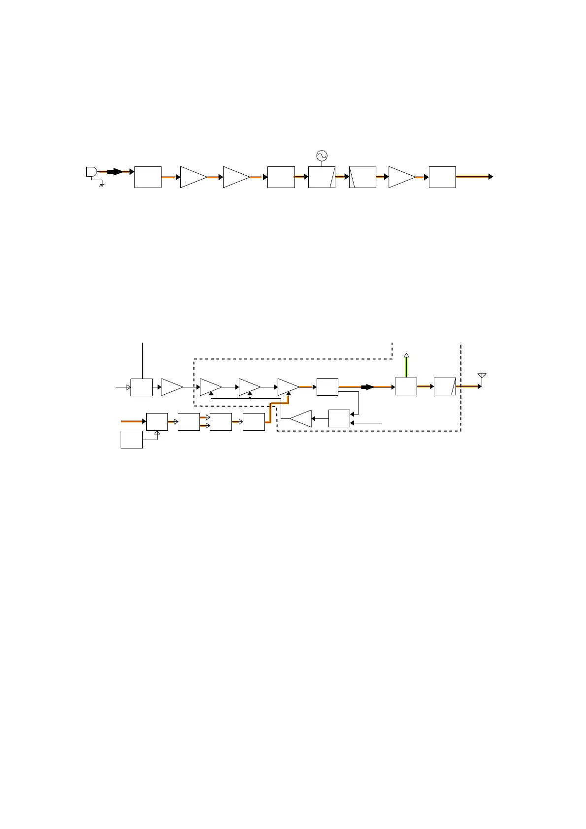
• TX AF CIRCUITS
• AM MODULATION AND TX AMPLIFIER CIRCUITS

 Loading...


