3 - 5
Pin
No.
Line
name
Description I/O
1 EC [EC] key. (pulled up) I
2 DIAL [DIAL] key. (pulled up) I
3 BEEP Beep audio. O
4 MONI [VOL] switch. (push) I
7 PTT1_0 External [PTT1/2] keys. I
15 RESET Reset signal from the reset IC (F: IC3). I
19 REG_C2
Regulator control signal to the +16V
regulator (M: IC75).
"Low"=ON
O
24 INCOM_0 External intercom switch (pulled up). I
25 SFT
Clock frequency shift signal to system
clock oscillator (F: Q6).
O
34–
37
V3–V0 Power supply for EL display (F: DS11). O
40 SCK Serial clock to the EEPROM (F:IC5). O
43 SDN1
Phase-A signal from rotary encoder (S1;
innner).
I
44 SUP1
Phase-B signal from rotary encoder (S1;
innner).
I
45 SDN2
Phase-A signal from rotary encoder (S1;
outer).
I
46 SUP2
Phase-B signal from rotary encoder (S1;
outer).
I
52 DATA_IC11 Serial data to the LED driver (F: IC15). O
53 CLK_IC12 Serial clock to the LED driver (F: IC15). O
54–
56
A–C I/O setting signals to the logic IC (M: IC49). O
57 CDC
Common serial clock/data output to MAIN
UNIT control siganal.
O
67–
82
D0–D15
EL display driver (F: IC6, IC7) control data
bus.
I/O
88 REM_0 External [REMOTE] key. (pulled up) I
89 RSSI RSSI signal from the FM IF IC (M: IC39). I
90 NOISE Noise signal from the FM IF IC (M: IC39). I
91 VOX1
VOX (pilot side) signal from the VOX
detector (M: IC3, D16).
I
92 VOX2
VOX (co-pilot side) signal from the VOX
detector (M: IC3, D17).
I
93 VR Volume level from the VR (VR UNIT; R1). I
94 PHOTO
Luminescence level from light sensor (F:
IC9, D2).
I
95 UL
Unlock signal from PLL IC (M: IC47).
"Low"=PLL unlocked.
I
96 SWAP [ ] key. (pulled up) I
97 RCL [RCL] key. (pulled up) I
98 MEM [MEM] key. (pulled up) I
99 DUAL [DUAL] key. (pulled -up) I
Pin
No.
Line
name
Description
8 SEND
TX voltage line control signal to the 8T2 switch
(M: Q32).
"Low"=While transmitting.
9 VCO1
TX VCO control signal to the VCO switch (M: Q2).
"High"=TX VCO is selected.
10 VCO2
RX VCO control signal to the VCO switch (M: Q3).
"High"=RX VCO is selected.
11 AM/FM
RX mode toggling signal to the AM/FM switch
(M: Q48).
"Low"=AM mode is selected.
12 FIL1
1st IF fi lter (M: FI3, BW=20 kHz) select signal.
"Low"=FI3 (BW=20 kHz) is selected.
13 FIL2
1st IF fi lter (M: FI4, BW=9 kHz) select signal.
"Low"=FI4 (BW=9 kHz) is selected.
14 MM
AF mute signal to the MUTE SW (M: Q58,
Q59).
"High"=AF line is muted.
16 ANL
ANL circuit control signal to the ANL switch (M: IC70).
"Low"=ANL function is activated.
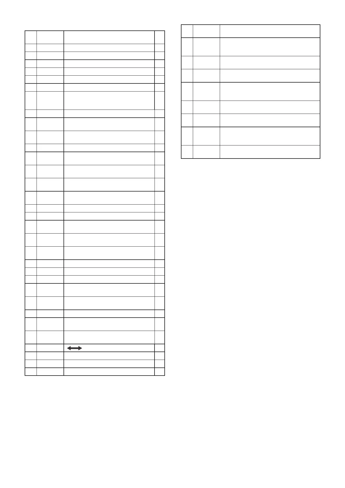
3-5 PORT ALLOCATIONS
• CPU (F: IC4)
• EXPANDER (M: IC48)

 Loading...


