Maximum indi-
cation
At the point
where the noise
audio just disap-
pears.
Squelch opens
Desired level
1
1
2
1
• Operating frequency : 136.000 MHz
• Connect an SSG to the antenna con-
nector and set as:
Level : 5.6 µV* (–92 dBm)
Modulation : OFF
• Connect a 4 Ω load to the external
speaker jack.
• Enter
Initial Set Mode
No. 5.
Refer to page 5-2 for details.
• Receiving
• Make sure no signal is being applied
to the antenna connector.
• Enter
Initial Set Mode
No. 2.
Refer to page 5-2 for details.
• Operating frequency : 136.000 MHz
• Receiving
• Connect an SSG to the antenna con-
nector and set as:
Level : 0.25 µV* (–119 dBm)
Deviation : ±3.5 kHz
Modulation : 1 kHz
• Receiving
• Enter
Initial Set Mode
No. 3.
Refer to page 5-2 for details.
• Operating frequency : Any
• Receiving
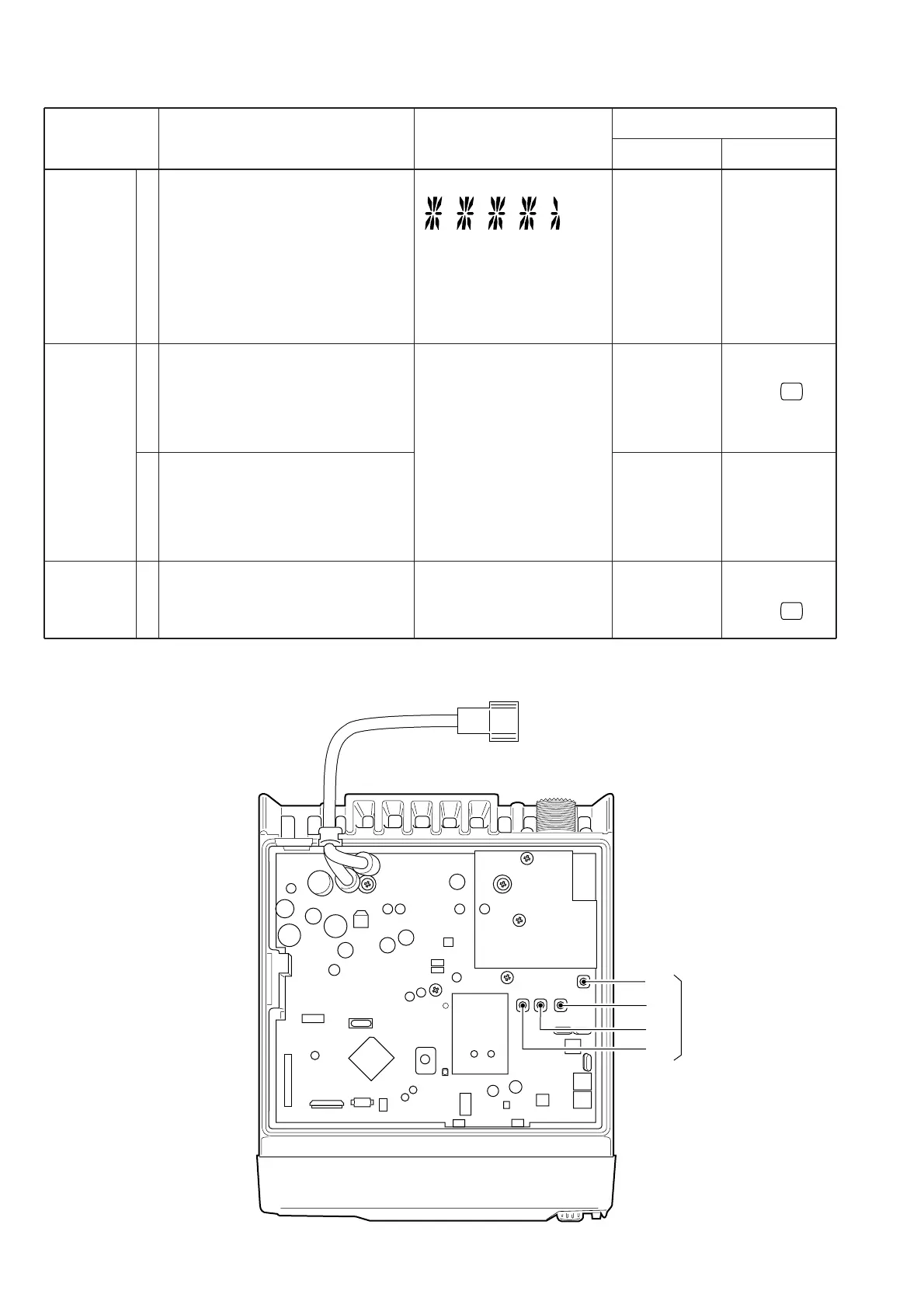
5-4 RECEIVER ADJUSTMENT
RECEIVER
SENSITIVITY
NOISE
SQUELCH
THRESHOLD
POINT
BEEP
LEVEL
Number digits in the LCD
Speaker output
Speaker output
ADJUSTMENT ADJUSTMENT CONDITIONS
VALUE ADJUST
MEASUREMENT
METHOD
ADJUSTMENT
*This output level of the standard signal generator (SSG) is indicated as SSG’s open circuit.
 Loading...