5 - 5
OUTPUT
POWER
FM
DEVIATION
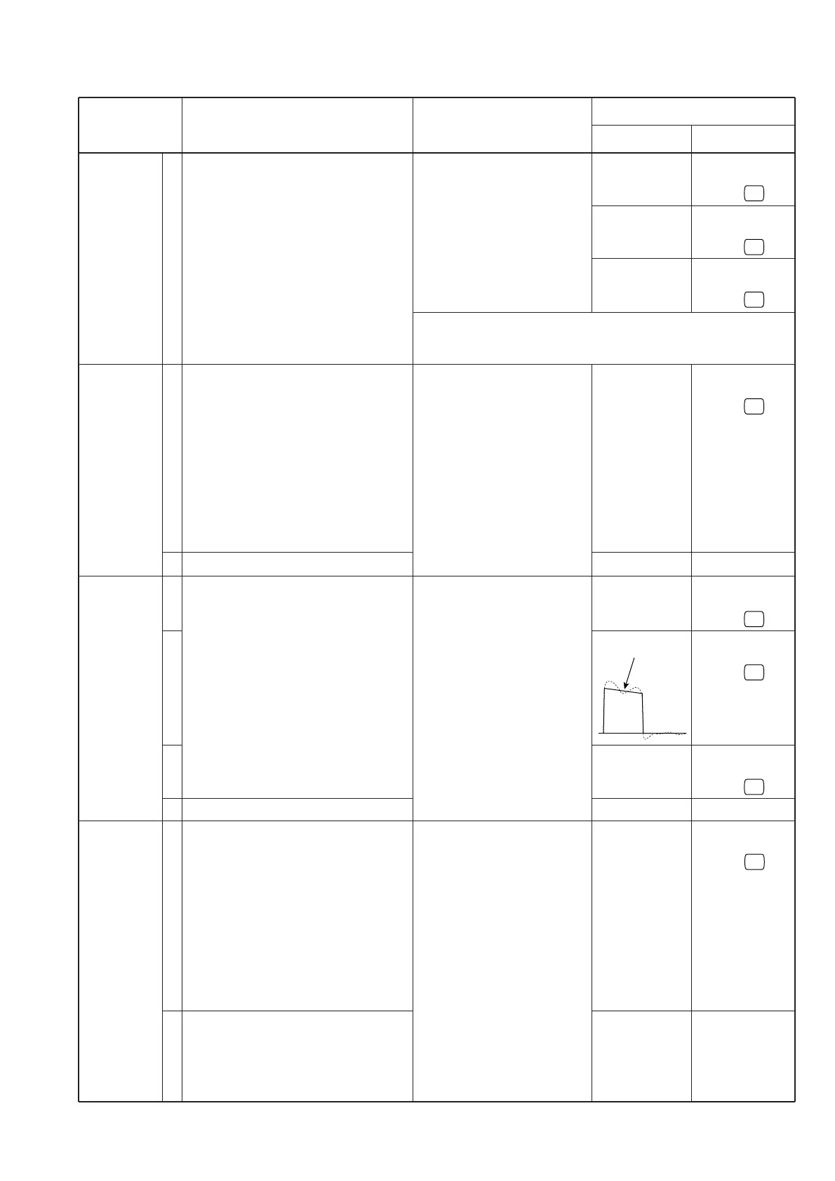
DTCS WAVE
FORM AND
DEVIATION
CTCSS
TONE
DEVIATION
25 W
10 W
2.5 W
±4.1 kHz
±1.75–±2.2 kHz
Maximum wave
form
±0.7 kHz
±0.25–±0.5 kHz
±0.7 kHz
±0.25–±0.5 kHz
Connect an RF power meter to
the antenna connector.
Connect an FM deviation
meter to the antenna connec-
tor through an attenuator.
Connect an FM deviation
meter with an oscilloscope to
the antenna connector through
an attenuator.
Connect an FM deviation
meter to the antenna connec-
tor through an attenuator.
• Operating frequency : 146.000 MHz
• Enter
Initial Set Mode
No. 6.
Refer to page 5-2 for details.
• Operating frequency : 146.000 MHz
• Enter
Initial Set Mode
No. 4.
Refer to page 5-2 for details.
• Connect an audio generator to the
microphone connector and set as:
1 kHz/35 mV
• Set an FM deviation meter as:
HPF : OFF
LPF : 20 kHz
De-emphasis: OFF
Detector : (P–P)/2
• Wide/Narrow setting : Wide
• Wide/Narrow setting : Narrow
• Operating frequency : 146.000 MHz
• Enter
Initial Set Mode
No. 4.
Refer to page 5-2 for details.
• No AF signals are applied to the micro-
phone connector.
• Set an FM deviation meter as:
HPF : OFF
LPF : 20 kHz
De-emphasis: OFF
Detector : (P–P)/2
• Wide/Narrow setting : Wide
• DTCS code : 007
• Wide/Narrow setting : Narrow
• Operating frequency : 146.000 MHz
• Enter
Initial Set Mode
No. 4.
Refer to page 5-2 for details.
• No AF signals are applied to the micro-
phone connector.
• Set an FM deviation meter as:
HPF : OFF
LPF : 20 kHz
De-emphasis: OFF
Detector : (P–P)/2
• Wide/Narrow setting : Wide
• CTCSS tone frequency: 67.0 Hz
• Wide/Narrow setting : Narrow
5-5 TRANSMITTER ADJUSTMENT
ADJUSTMENT ADJUSTMENT CONDITIONS
VALUE ADJUST
MEASUREMENT
METHOD
ADJUSTMENT
1
1
2
1
2
3
4
1
2
NOTE: When the RF output power cannot be set with this proce-
dure, cloning may be necessary to cancel the output power
setting.
 Loading...