4-8
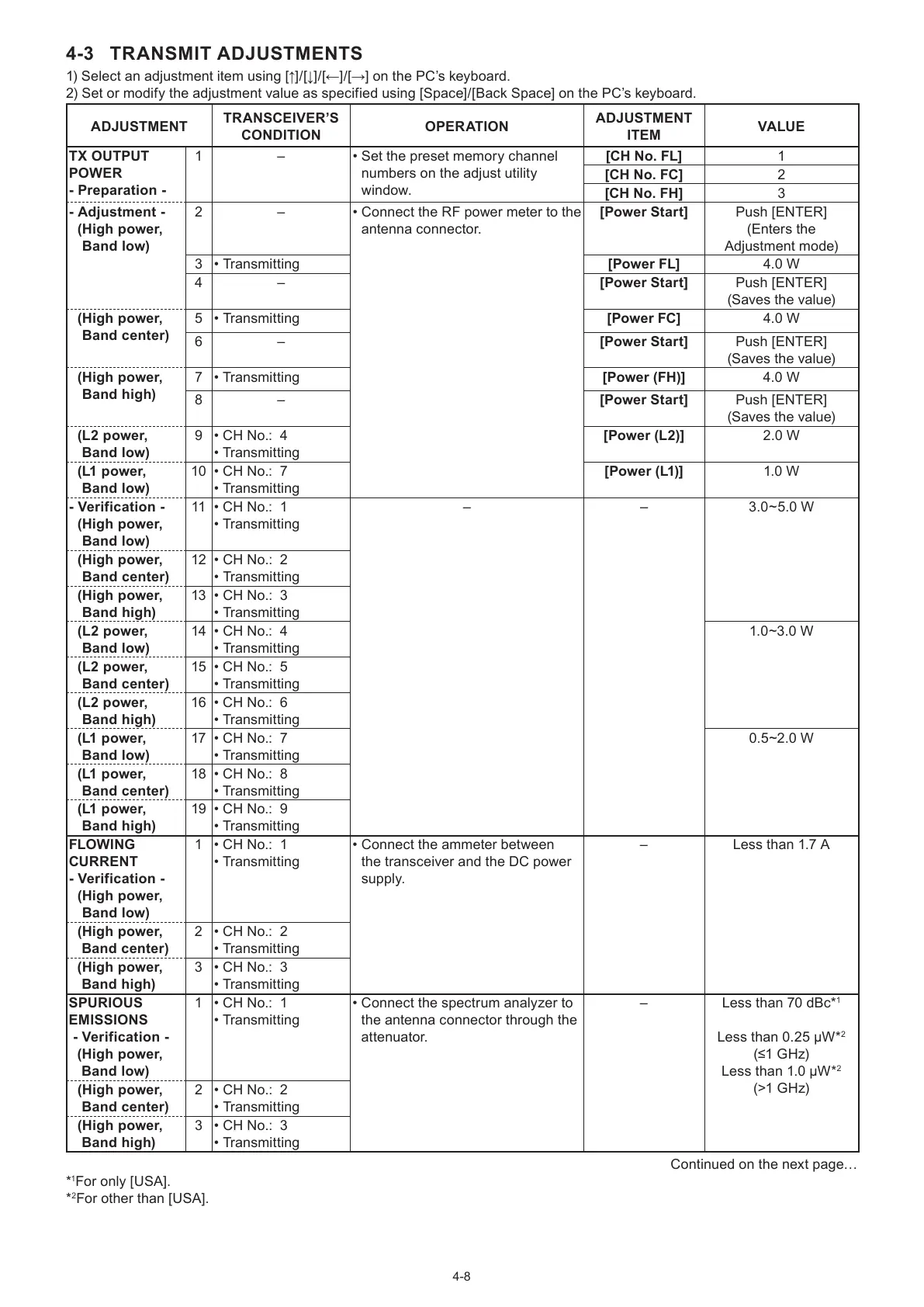
4-3 TRANSMIT ADJUSTMENTS
1) Select an adjustment item using [↑]/[↓]/[←]/[→] on the PC’s keyboard.
2) Set or modify the adjustment value as specified using [Space]/[Back Space] on the PC’s keyboard.
ADJUSTMENT
TRANSCEIVER’S
CONDITION
OPER ATION
ADJUSTMENT
ITEM
VALUE
TX OUTPUT
POWER
- Preparation -
1 – • Set the preset memory channel
numbers on the adjust utility
window.
[CH No. FL] 1
[CH No. FC] 2
[CH No. FH] 3
- Adjustment -
( High power,
Band low)
2 – • Connect the RF power meter to the
antenna connector.
[Power Start] Push [ENTER]
(Enters the
Adjustment mode)
3 • Transmitting [Power FL] 4.0 W
4 – [Power Start] Push [ENTER]
(Saves the value)
( High power,
Band center)
5 • Transmitting [Power FC] 4.0 W
6 – [Power Start] Push [ENTER]
(Saves the value)
( High power,
Band high)
7 • Transmitting [Power (FH)] 4.0 W
8 – [Power Start] Push [ENTER]
(Saves the value)
( L2 power,
Band low)
9 • CH No.: 4
• Transmitting
[Power (L2)] 2.0 W
( L1 power,
Band low)
10 • CH No.: 7
• Transmitting
[Power (L1)] 1.0 W
- Verification -
( High power,
Band low)
11 • CH No.: 1
• Transmitting
–
–
3.0~5.0 W
( High power,
Band center)
12 • CH No.: 2
• Transmitting
( High power,
Band high)
13 • CH No.: 3
• Transmitting
( L2 power,
Band low)
14 • CH No.: 4
• Transmitting
1.0~3.0 W
( L2 power,
Band center)
15 • CH No.: 5
• Transmitting
( L2 power,
Band high)
16 • CH No.: 6
• Transmitting
( L1 power,
Band low)
17 • CH No.: 7
• Transmitting
0.5~2.0 W
( L1 power,
Band center)
18 • CH No.: 8
• Transmitting
( L1 power,
Band high)
19 • CH No.: 9
• Transmitting
FLOWING
CURRENT
- Verification -
( High power,
Band low)
1 • CH No.: 1
• Transmitting
• Connect the ammeter between
the transceiver and the DC power
supply.
– Less than 1.7 A
(High power,
Band center)
2 • CH No.: 2
• Transmitting
(High power,
Band high)
3 • CH No.: 3
• Transmitting
SPURIOUS
EMISSIONS
- Verification -
(High power,
Band low)
1 • CH No.: 1
• Transmitting
• Connect the spectrum analyzer to
the antenna connector through the
attenuator.
– Less than 70 dBc*
1
Less than 0.25 μW*
2
(≤1 GHz)
Less than 1.0 μW*
2
(>1 GHz)
(High power,
Band center)
2 • CH No.: 2
• Transmitting
(High power,
Band high)
3 • CH No.: 3
• Transmitting
Continued on the next page…
*
1
For only [USA].
*
2
For other than [USA].

 Loading...