4-19
ADJUSTMENT
TRANSCEIVER’S
CONDITION
OPER ATION
ADJUSTMENT
ITEM
VALUE
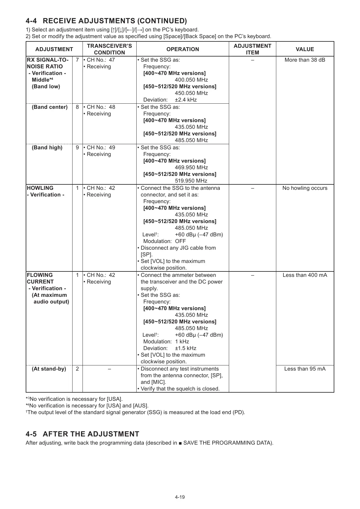
RX SIGNAL-TO-
NOISE RATIO
- Verification -
Middle*
4
(Band low)
7 • CH No.: 47
• Receiving
• Set the SSG as:
Frequency:
[400~470 MHz versions]
400.050 MHz
[450~512/520 MHz versions]
450.050 MHz
Deviation: ±2.4 kHz
– More than 38 dB
(Band center) 8 • CH No.: 48
• Receiving
• Set the SSG as:
Frequency:
[400~470 MHz versions]
435.050 MHz
[450~512/520 MHz versions]
485.050 MHz
(Band high) 9 • CH No.: 49
• Receiving
• Set the SSG as:
Frequency:
[400~470 MHz versions]
469.950 MHz
[450~512/520 MHz versions]
519.950 MHz
HOWLING
- Verification -
1 • CH No.: 42
• Receiving
• Connect the SSG to the antenna
connector, and set it as:
Frequency:
[400~470 MHz versions]
435.050 MHz
[450~512/520 MHz versions]
485.050 MHz
Level
†
: +60 dBµ (–47 dBm)
Modulation: OFF
• Disconnect any JIG cable from
[SP].
• Set [VOL] to the maximum
clockwise position.
– No howling occurs
FLOWING
CURRENT
- Verification -
( At maximum
audio output)
1 • CH No.: 42
• Receiving
• Connect the ammeter between
the transceiver and the DC power
supply.
• Set the SSG as:
Frequency:
[400~470 MHz versions]
435.050 MHz
[450~512/520 MHz versions]
485.050 MHz
Level
†
: +60 dBµ (–47 dBm)
Modulation: 1 kHz
Deviation: ±1.5 kHz
• Set [VOL] to the maximum
clockwise position.
– Less than 400 mA
(At stand-by) 2 – • Disconnect any test instruments
from the antenna connector, [SP],
and [MIC].
• Verify that the squelch is closed.
Less than 95 mA
*
3
No verification is necessary for [USA].
*
4
No verification is necessary for [USA] and [AUS].
†
The output level of the standard signal generator (SSG) is measured at the load end (PD).
4-5 AFTER THE ADJUSTMENT
After adjusting, write back the programming data (described in ■ SAVE THE PROGRAMMING DATA).
4-4 RECEIVE ADJUSTMENTS (CONTINUED)
1) Select an adjustment item using [↑]/[↓]/[←]/[→] on the PC’s keyboard.
2) Set or modify the adjustment value as specified using [Space]/[Back Space] on the PC’s keyboard.

 Loading...