4 - 4
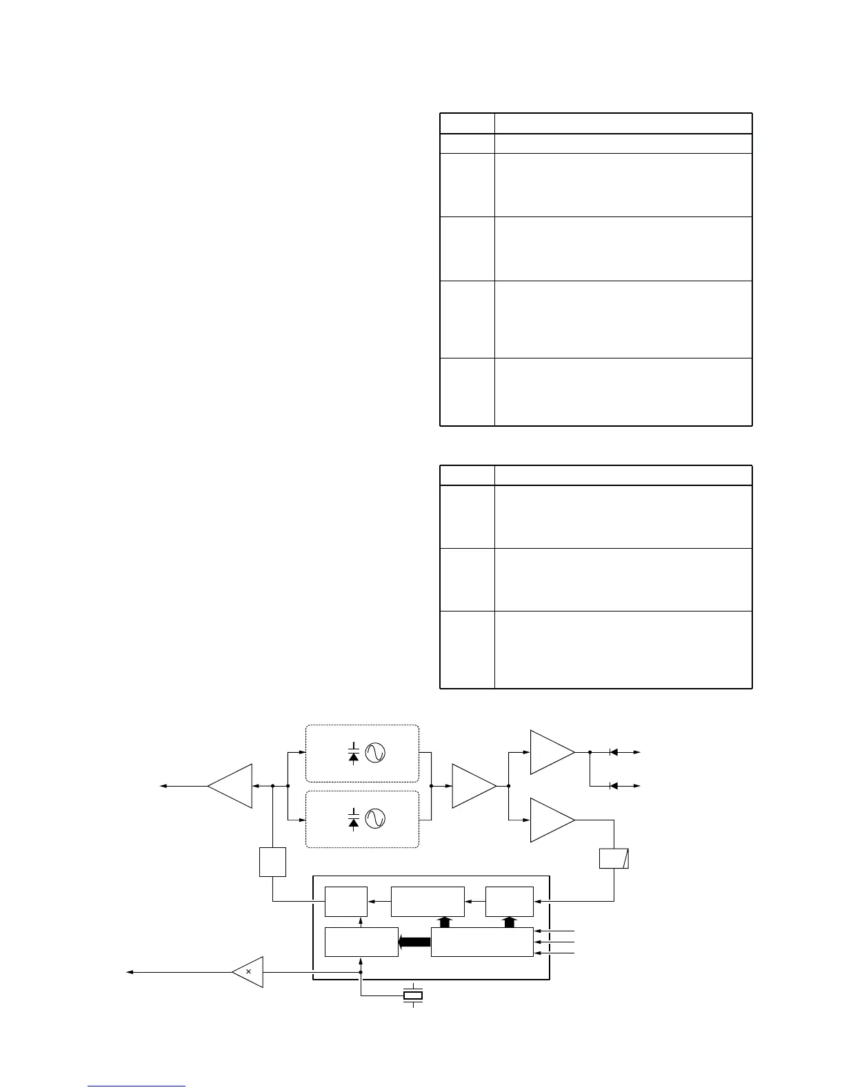
4-3-2 VCO CIRCUIT (MAIN UNIT)
The VCO circuit contains a separate RX VCO (Q13, D16)
and TX VCO (Q14, D17). The oscillated signal is amplified
at the buffer amplifiers (Q10, Q11) and is then applied to the
T/R switch (D14, D15). Then the receive 1st LO (Rx) signal
is applied to the 1st mixer (Q3) and the transmit (Tx) signal
to the YGR amplifier circuit (Q9).
A portion of the signal from the buffer amplifier (Q11) is fed
back to the PLL IC (IC4, pin 8) via the buffer amplifier (Q12)
as the comparison signal.
LINE
VCC
+5V
S5V
R5V
T5V
DESCRIPTION
The voltage from the connected battery pack.
Common 5 V converted from the VCC line at the
+5 regulator circuit (IC9). The output voltage is
supplied to buffer amplifiers (Q18), FRONT unit,
etc.
Common 5 V converted from the VCC line at the
S5 regulator circuit (Q23–Q25). The output volt-
age is supplied to the ripple filter (Q17), PLL IC
(IC4), FRONT unit, etc.
Receive 5 V converted from the S5V line at the
R5 regulator circuit (Q22). The output voltage is
supplied to the tripler (Q34), FM IF IC (IC1), IF
amplifier (Q4), VCO switch (Q15, Q16), 1st
mixer (Q3), etc.
Transmit 5 V converted from the S5V line at the
T5 regulator circuit (Q21). The output voltage is
supplied to the YGR amplifier (Q5, Q9), drive
amplifier (Q8), APC amplifier (IC2), etc..
LINE
VCC
CPU5
S5V
DESCRIPTION
Same voltage as VCC line on the MAIN unit is
applied to the FRONT unit via the J401, pins 1,
2 (FRONT unit). The voltage is supplied to the
[PWR] switch controller (Q401, Q402).
Same voltage as +5V line on the MAIN unit is
applied to the FRONT unit via the J401, pin 4
(FRONT unit). The voltage is supplied to the
CPU (IC401), reset IC (IC408), etc.
Same voltage as S5V line on the MAIN unit is
applied to the FRONT unit via the J401, pin 5
(FRONT unit). The voltage is supplied to the mic
mute circuit (IC406), AF mute circuit (Q403-
Q406, IC406), etc.

 Loading...