4 - 5
4-5 OTHER CIRCUITS
4-5-1 COMPANDER CIRCUIT (MAIN UNIT)
IC-F510 series have compander circuit which can improve
S/N ratio and become wide dynamic range. The circuit is
composed in the compander IC (IC14).
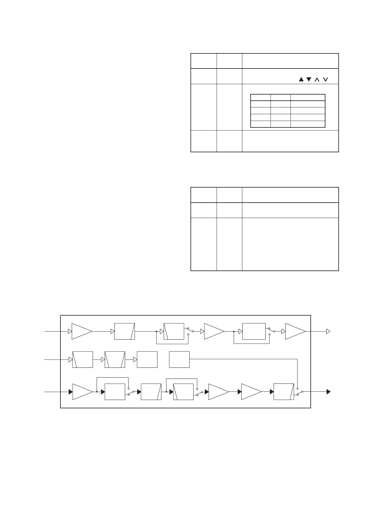
(1) IN CASE OF RECEIVING
The demodulated AF signals from the FM IF IC (IC1, pin
9) are applied to the amplifi er section in the compander IC
(IC14, pin 3), and then pass through the low-pass fi lter and
high-pass fi lter sections to suppress unwanted signals. The
fi ltered signals are applied to the expander circuit to expand
AF signals.
The output signals from the compander IC (IC14, pin 38)
is applied to the AF amplifier circuit after amplified at the
amplifi er section.
(2) IN CASE OF TRANSMITTING
The audio signals from the microphone amplifer (FRONT
UNIT; IC2) are applied to the compander IC (IC14, pin 12)
via the D/A converter (IC6, pins 9, 10). The signals are
amplified at the amplifier section, and are then applied to
the compressor circuit to compress the audio signals. The
signals are pass through the low-pass filter and high-pass
filter sections and are then applied to the limiter amplifer
section after being passed through the high-pass filter
section.
The filtered signals pass through the splatter filter section,
and are then applied to the modulation circuit (D18) via the
PM/FM switch (IC15, pins1, 6, 7) and D/A converter (IC6,
pins 21, 22).
• COMPANDER IC BLOCK DIAGRAM
4-6 PORT ALLOCATIONS
4-6-1 OUTPUT EXPANDER (FRONT UNIT; IC1)
Pin
number
Port
name
Description
1–3
KS0–
KS2
Output ports for the programmable
function keys (P0–P4, , , , ).
4, 5
DIM1,
DIM2
Output LCD backlight control signals.
7 HORN
Outputs external device control signal.
High: When matched 2/5 tone sig-
nals are received.
DIM1 DIM2 LIGHT
HIGH HIGH ON
HIGH LOW OFF
LOW HIGH DIM
LOW LOW OFF
4-6-2 D/A CONVERTER (MAIN UNIT; IC7)
Pin
number
Port
name
Description
1–3 T1–T3
Output the bandpass filters (D4, D8,
D9) tuning signals.
4T4
• Outputs the bandpass filter (D10)
tuning signal while receiving.
• Outputs the TX power control
signal which selects High, Low1,
Low2 of TX power while trans-
mitting. The output signal is ap-
plied to the APC amplifier (IC2,
pin 1).
EXPANDER
DEMOD
MSK
AMP
LPF
LPF
HPF
AMP AMP
LPF
TX OUT
RX OUT
LIMIT
AMP
AMP
HPF
HPF
AMP
BPF
MOD
MSK
COM-
PRESSOR
3
TX IN
MSK IN
RX IN
5
12
6
38
 Loading...