5 - 4
5-2 SOFT WARE ADJUSTMENT
Select an operation using [
↑
] / [
↓
] keys, then set specifi ed value using [
←
] / [
→
] keys on the connected computer keyboard
ADJUSTMENT ADJUSTMENT CONDITION
MEASUREMENT
VALUE
UNIT OPERATION
PLL LOCK
VOLTAGE
1 • Operating CH.
• Receiving
: CH 1 PC
screen
Click [Reload (F5)] button, then
check the "LVIN" item on the
CS-F70/F1700 ADJ's screen.
0.75–1.45 V
(Verify)
2 • Operating CH.
• Receiving
: CH 2 0.55–1.35 V
(Verify)
3 • Operating CH. : CH 3 0.55–1.15 V
(Verify)
• Connect an RF power meter or 50
Ω
dummy load to the antenna connector.
• Transmitting
REFERENCE
FREQUENCY
[REF]
• Operating CH. : CH 3 Top
panel
Loosely couple a frequency
counter to the antenna connec-
tor.
470.000000 MHz [L]
520.000000 MHz [H]
±100 Hz
• Connect an RF power meter or 50
Ω
dummy load to the antenna connector.
• Transmitting
DSP
REFERENCE
FREQUENCY*
[Dig REF]
• Operating CH. : CH 8 DSP
unit
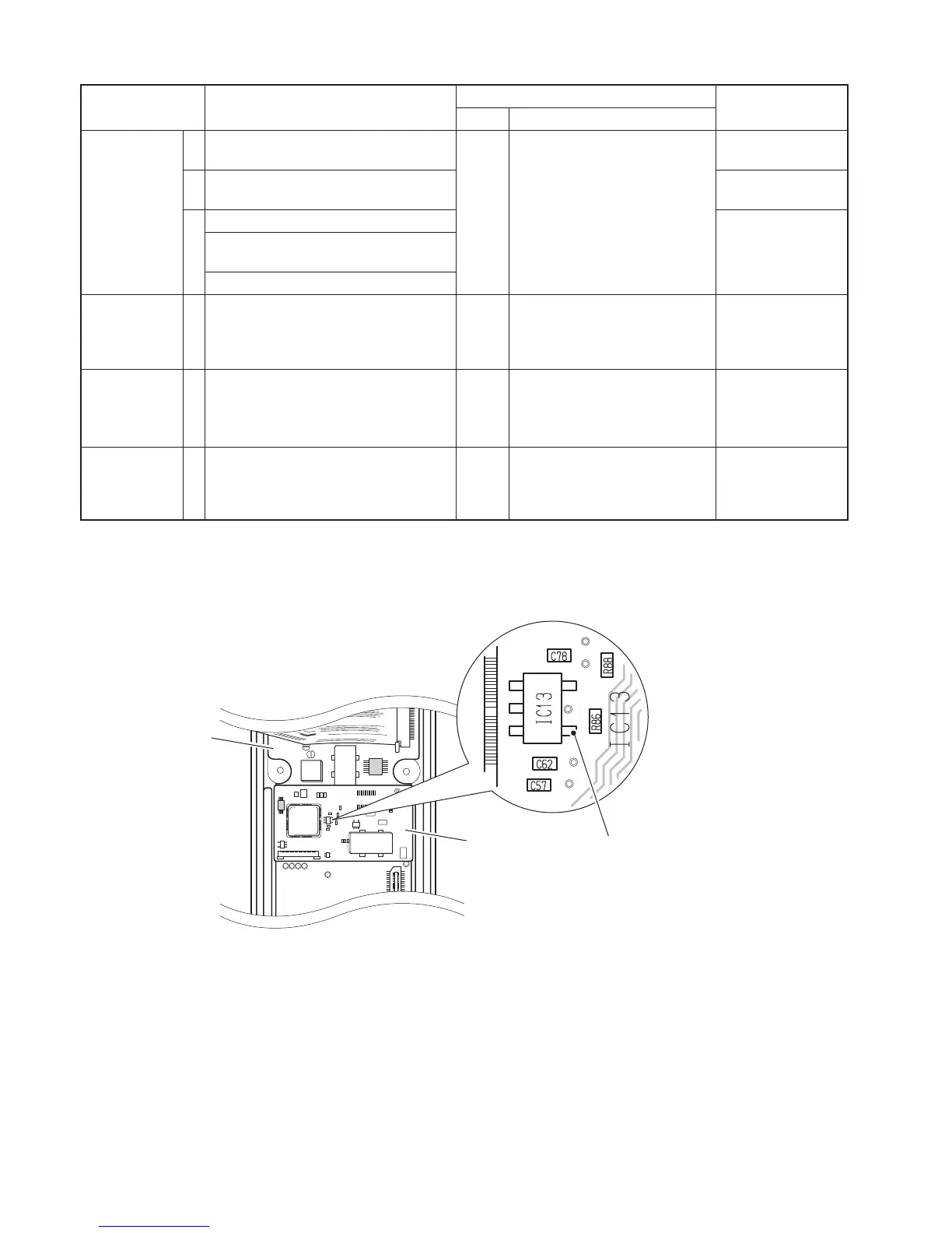
Connect a frequency counter
to the pin 4 of IC13 on the DSP
unit through a 1000 pF capacitor.
(see the illust below)
12.288000 MHz
• Receiving
BASE BAND
CENTER
VOLTAGE*
[Dig DA]
• Operating CH.
• Receiving
: CH 8 PC
screen
Set the "Dig DA" item to 70.
*; IC-F80DT/DS only
DSP REFERENCE FREQUENCY
CHECK POINT (
IC-13, pin 4)
DSP UNIT
MAIN UNIT
 Loading...