4-4
• FREQUENCY SYNTHESIZER CIRCUIT
LO
AMP
LPFDDS1/2AMP AMP AMP
LO
AMP
X2 AMP
BPF
BPF
BUFF
BPF
DDS
LPF
LPF
HPF
LPF
BPFAMP
BPF
32.0MHz
3rd LO=419.0 kHz
2nd LO=64.0 MHz
1st LO=64.485-94.455 MHz
64 MHz
Q1410
X1601
IC1605
(TX/RX Freq.= 0.03-15 MHz)
(TX/RX Freq.= 15-30 MHz)
64.485-79.455MHz
0.03–15 MHz 15–30 MHz
79.455-94.455MHz
Q1601
IC1602
IC1606
IC1703
D1702 D1703
32.2425—47.2275 MHz
IC1604
Q1404-Q1407
IC1402
fc=94.455 MHz
REF OSC
32MHz
IC1705
IC1404
D1706
L1719, L1722, L1724,
L1726, L1728, L1730,
C1744, C1746, C1749,
C1750, C1752, C1754,
C1755, C1760, C1762,
C1763, C1767, C1768,
C1772, C1773, C1775,
C1778
D1707
D1704
D1704,D1706
Diode SW
to pass
Components
Operating
frequenct
D1705
D1705,D1707
L1720, L1723, L1725,
L1727, L1729, L1731,
L1732, C1745, C1747,
C1751, C1753,
C1756–C1759
,
C1761, C1764, C1765,
C1769, C1770, C1774,
C1776, C1779
D1813
D1812
256 MHz
X8
X2
IC1603
IC1601
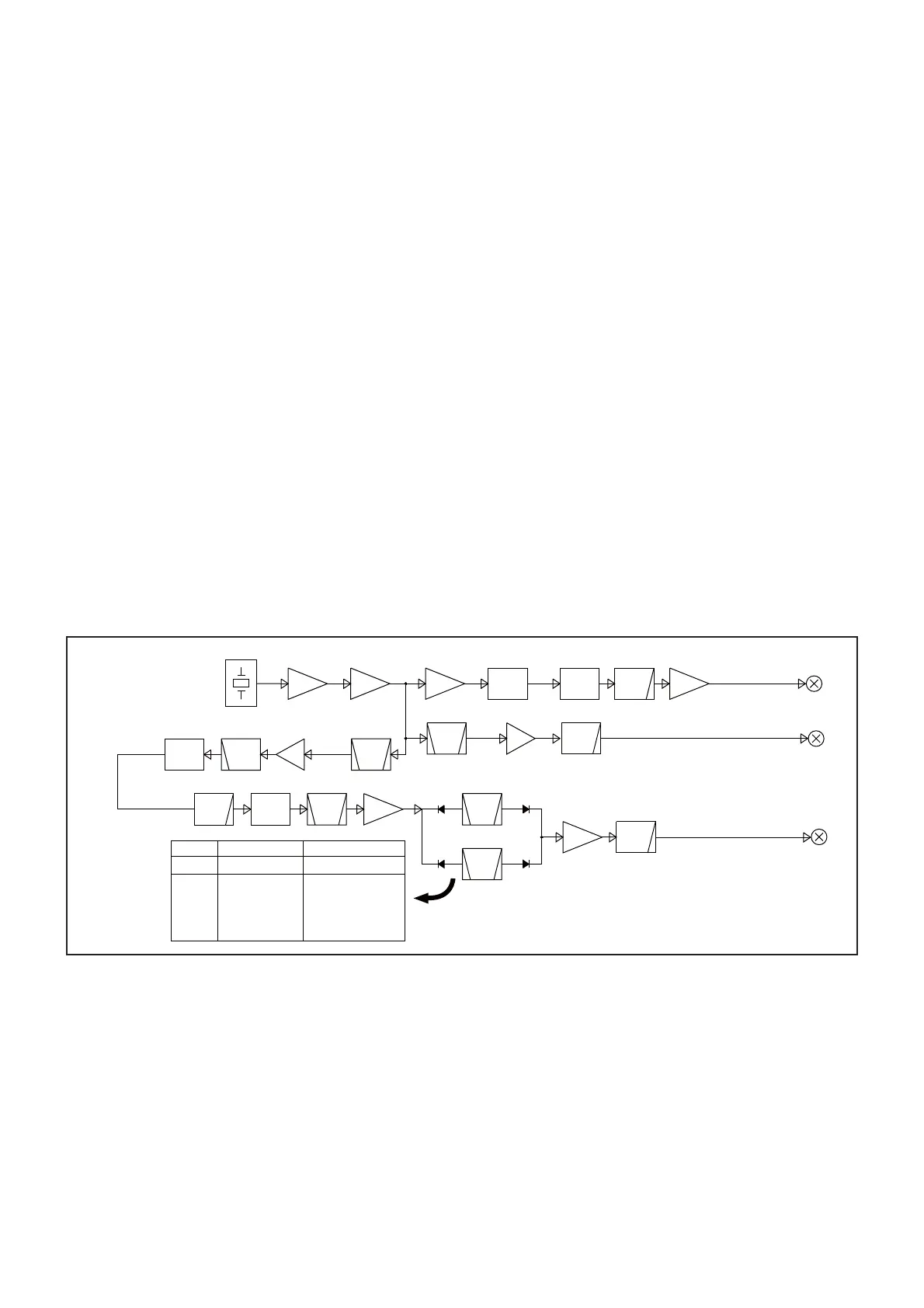
4-3 FREQUENCY SYNTHESIZER CIRCUITS
The 3rd TX/RX LO signal (MAIN-A UNIT)
The 32 MHz reference frequency signal, which is gener-
ated by X1601, is amplified by the buffer (Q1601) and two
AMPs (IC1604 and IC1605), and then applied to the divider
(IC1603). The divided reference frequency signal is applied
to the DDS IC (IC1601).
Using the applied DDS master clock signal as the reference,
the DDS IC generates the 419 kHz 3rd RX/TX LO signal.
The generated 3rd RX/TX LO signal is passed through the
LPF (L1601, L1603, C1601, C1604, C1605, C1608), and
amplified by the AMP (IC1404), and then applied to the 1st
TX/RX IF mixer (IC1402).
The 2nd TX/RX LO signal (MAIN-A UNIT)
The 32 MHz reference frequency signal, which is gener-
ated by X1601, is amplified by the buffer (Q1601) and AMP
(IC1604), and then doubled by the doubler (L1617, L1620,
L1622–L1624, C1642, C1644, C1647, C1650, C1653,
C1655, C1658, C1659, C1661–C1664), resulting in the 64
MHz 2nd TX/RX LO signal.
The 2nd TX/RX LO signal is amplified by the LO AMP
(IC1602), and then applied to the 2nd TX/RX IF mixer
(D1812, D1813), through the LPF (L1602, L1604, C1602,
C1603, C1606, C1607, C1609).
The 1st TX/RX LO signal
The 32 MHz reference frequency signal, which is gener-
ated by X1601, is amplified by the buffer (Q1601) and
AMP (IC1604), and then applied to the BPF (L1608,
L1612–L1615, L1618, L1626, C1666, C1620, C1623,
C1625, C1629, C1631, C1634, C1636, C1638, C1640,
C1641, C1643, C1646, C1649, C1652, C1654), resulting in
the 256 MHz DDS master clock signal.
The clock signal is amplified by the AMP (IC1606), and then
applied to the DDS IC, through the HPF (L1627, L1628,
L1701, C1667, C1668, C1702, C1703).
Using the applied DDS master clock signal as the reference,
the DDS IC generates the 32.2425–47.2275 MHz signal.
The generated signal is passed through the LPF (L1704,
L1706, C1711, C1713, C1718, C1720, C1722, C1723), and
doubled by the doubler (D1702, D1703), resulting in the
64.485-94.455 MHz 1st TX/RX LO signal.
The 1st TX/RX LO signal is passed through the BPF
(L1709–L1711, C1729. C1731–C1734, C1736), amplified by
the AMP (IC1705), passed through another BPF (See the
table below for the detail), and then applied to the LO AMP
(Q1410).
The amplified 1st TX/RX LO signal applied to the 1st TX/RX
IF mixer (IC1401/Q1404–Q1407), through the LPF (L1419,
L1422, C1437, C1444, C1445, C1448).
 Loading...