5-8
ADJUSTMENT
TRANSCEIVER’S
CONDITION
OPERATION
ADJUSTMENT
ITEM
VALUE
CM
COUPLER
1 • Channel: 22
• Mode: CW
• Receiving
• Test equipment
Connect the test equipment to
the antenna connector.
(Confi g Menu)* "RF Power"
"MID"
2 • Transmitting Simple 23/30
(Factory Menu)
"TX Middle Power"
30 W
3• Connect a digital voltmeter to
the check point “REF” on the
PA-A UNIT.
(PA-A UNIT) C5110
Minimum
voltage
*; Enter the Confi g Menu as shown below.
1) Push [
] to return to the Main Menu.
2) Select “Setmode” and push [
] to enter, and then select “Confi g” using [
]/[
].
3) Select “RF Power,” and then set the TX power.
4) Return to the Factory Menu to continue the adjustment.
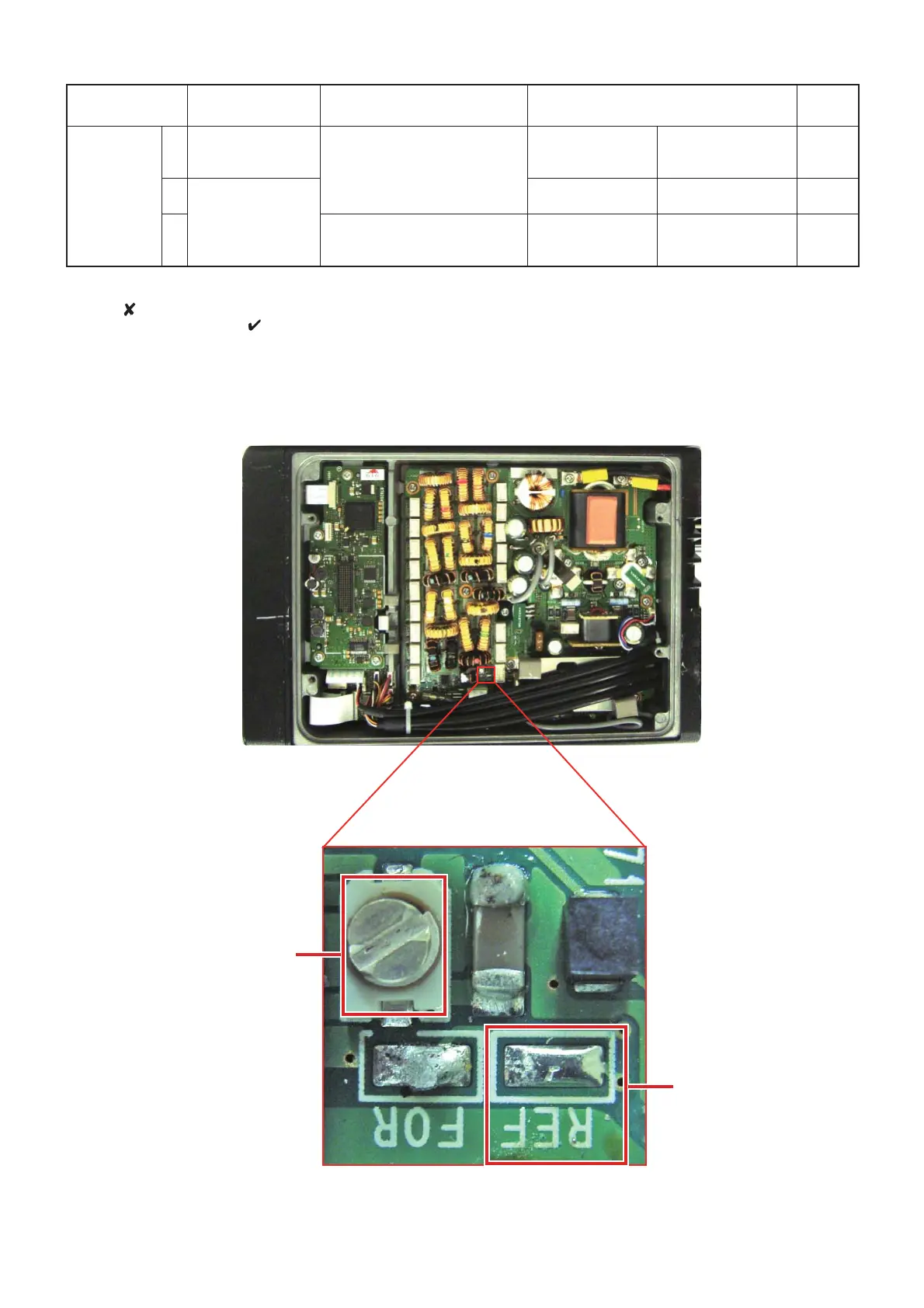
5-3 TRANSMIT ADJUSTMENTS (Continued)
• ADJUSTMENT POINT ON THE PA-A UNIT
CM COUPLER
ADJUSTMENT POINT
(C5110)
CM COUPLER
CHECK POINT
(REF)
 Loading...