4-5
Pin
No.
Line
Name
Description I/O
2 LEDC LCD dimmer control. O
7 RESET
CPU reset.
L=The CPU is reset.
I
17 TXD L-bus communication line to the MAIN CPU. O
18 RXD L-bus communication line to the MAIN CPU. I
19 LRES
LCD driver reset.
L=The driver is reset.
I
27 RXD
L-bus wakeup line.
L=Wakeup.
I
28 IOK
[
] input.
L=Pushed.
I
29 P3K
[
] input.
L=Pushed.
I
30 P2K
[
] input.
L=Pushed.
I
31 P1K
[
] input.
L=Pushed.
I
32 DNK
[
–] input.
L=Pushed.
I
33 UPK
[
+] input.
L=Pushed.
I
34 EMGK
[
] input.
L=Pushed.
I
35 MENK
[
] input.
L=Pushed.
I
36 CALK
[
] input.
L=Pushed.
I
41 LCS
LCD driver control.
L=Enabled.
O
42–49 DB0–DB7 LCD driver control. (Parallel data bus) O
51 LWR
LCD driver control.
L=Data write status.
O
52 LA0
LCD driver control.
H=In the address select mode.
O
55 LRD
LCD driver control.
L=Data read status.
O
56 FPWRS
8V power supply line control.
H=While the transceiver's power is ON.
O
57 MGAIN
MIC gain control.
H=The gain increases +20 dB.
O
58 T5K
[5 JKL] input.
L=Pushed.
I
59 T6K
[6 MNO] input.
L=Pushed.
I
60 T7K
[7 PRS/CLAR] input.
L=Pushed.
I
61 T8K
[8 TUV/CTALK] input.
L=Pushed.
I
62 T1K
[1 QZ] input.
L=Pushed.
I
63 T2K
[2 ABC] input.
L=Pushed.
I
64 T3K
[3 DEF/MODE] input.
L=Pushed.
I
65 T4K
[4 GHI] input.
L=Pushed.
I
66 TLK
[
] input.
L=Pushed.
I
67 TRK
[
] input.
L=Pushed.
I
68 CHDK
[
] input.
L=Pushed.
I
69 CHUK
[
] input.
L=Pushed.
I
70 T9K
[9 WXY/TUNER] input.
L=Pushed.
I
71 T0K
[0 _] input.
L=Pushed.
I
72 MUTK
[
@?/MUTE] input.
L=Pushed.
I
Pin
No.
Line
Name
Description I/O
73 SCNK
[# A
/
a /MNGR] input.
L=Pushed.
I
75 TEMP LCD temperature sensing voltage. I
76 MICL MIC input level sensing voltage. I
Pin
No.
Line
Name
Description I/O
2 BEEP Beep audio. O
3 TCOM
Tuner Scan control signal to the automatic
antenna tuner.
O
4 TSTART
Motor lock contol signal to the automatic
antenna tuner.
O
10 RESET
CPU reset signal.
L=The CPU is reset.
I
16 TXD
L-bus wakeup signal from the FRONT CPU.
L=Wakeup.
I
17 CWK
CW/FSK keing input.
L=Key down.
I
18 PTT
PTT input.
L=Pushed.
I
20 DRXD RX data from the DSP. I
21 DCLK Serial clock to the DSP. O
22 DTXD TX serial data to the DSP. O
23 HSK0
Hand shake signal to the DSP.
L=When the command is not granted.
I
25 FULL
ALE/SELCALL data full detect.
H=Data full.
I
26 VSQL
Voice squelch detection.
L=Voice detected. (Squelch open)
I
27 GPRXD GPS data (4800 bps). I
29 EXTXD External data output. O
30 EXRXD External data input. I
32 BPST
Beep status detection.
H=Detected.
I
33 RXD Data to the front CPU. O
34 TXD Data from the front CPU. I
35 CK Serial clock to the DDS IC. O
36 DT Serial data to/from the DDS IC. I/O
42 RD SRAM data read control. O
44 WR SRAM data write control. O
46 CWST
CW status detection.
L=While transmitting in the CW mode.
I
47 TUMB
Band switching control.
H= When the operating frequency is
13.3 MHz and higher.
O
48 CS0
SRAM chip select control.
L=Enabled.
O
52–70 A16–A0 SRAM control parallel bus. O
71 PWS
Power supply line "14V" control.
H=During the transceiver's power is ON.
O
73 DSKY Keying output. O
74 SEND
TX mute.
H=Mute.
O
75 MDA
Serial data to the D/A converter, shift reg-
ister and electronic volume.
O
76 MCK
Serial clock to the D/A converter, shift reg-
ister and electronic volume.
O
77 ECK EEPROM serial clock. O
78 ESIO EEPROM serial data. I/O
79–86 D7–D0 SRAM control parallel bus. I/O
87 RXS
RX power supply line control.
H=While receiving.
O
88 TXS
TX power supply line control.
H=While transmitting.
O
90 DCV External power source detect. I
91 TEMP
TX power AMP temperature sensing volt-
age.
I
92
KEYS External tuner key control. I
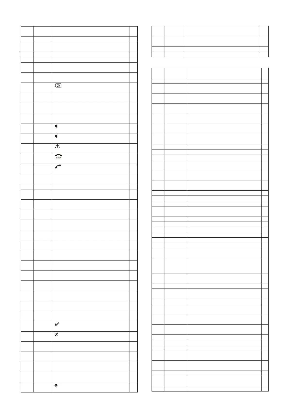
4-4 PORT ALLOCATIONS
• FRONT CPU (DISPLAY-A UNIT: IC6004)
• MAIN CPU (MAIN-A UNIT: IC1806)
 Loading...