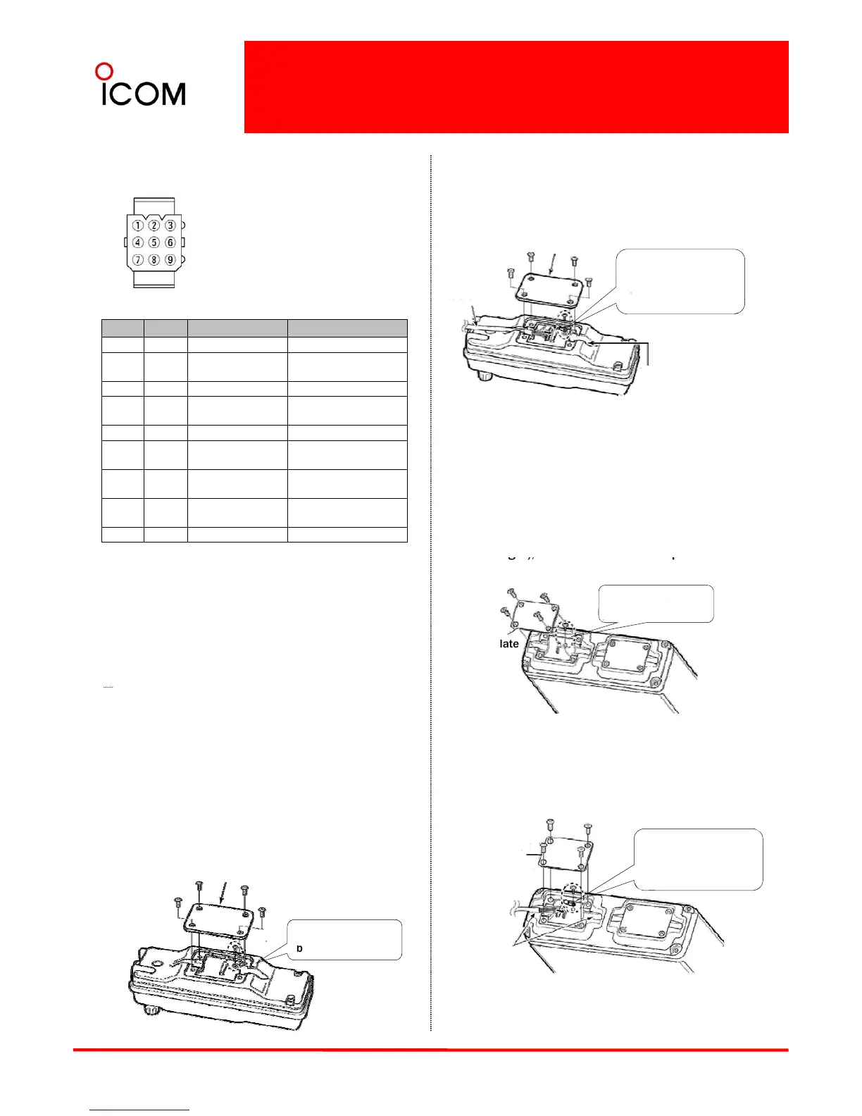
Speaker connector information
Connect the separation cable to the controller as
Speaker connector information
When the horn function is
activated, HORN1 and
HORN2 are shorted.
Connect the separation cable to the controller as
shown below.
• The cable can be inserted into either the left or
right grooves as desired.
Rear plate
Screw the removed
circuit board screw in
step 1 to connect the
Separation
Pin No.
Name Description Specifications
①
IGN IGSW cont. In 0 -Vcc
②
RXSP1 RX AF Out (BTL)
Output power : Max.20W
Impedance : 4
③
NC - -
④
HORN1 Horn drive cont.Out 0-VCC
Cable groove
Controller
cable terminal.
HORN2 Horn drive cont.Out 0
Vcc
⑥
RXSP2 RX AF Out (BTL)
Output power : Max.20W
Impedance : 4
⑦
PS1 AF Out to PA (BTL)
Output power : Max.20W
Impedance : 4
⑧
PS2 AF Out to PA (BTL)
Output power : Max.20W
Impedance : 4
⑨
GND Connects to ground. -
3After the cable connection, replace the removed
rear plate and the 4 screws, then connect the
opposite side of the separation cable to the main
unit.
Main unit
1Unscrew the 4 screws of the front plate (either the
left or ri
late from the
Separation cable connection
CAUTION: To avoid damage to the transceiver,
disconnect the DC power cable from the
transceiver before connecting the separation
cable.
NOTE: The following connections should be
main unit.
Front plate
Unscrew the circuit
board scew.
performed by your Icom dealer or distributor.
The supplied or optional separation cable is
required for the controller and the main unit
connection.
For the details on the separation cables,
see 3-5 Optional Accessories.
2Connect the opposite side of the separation cable
that is connected to the controller described on
the previous page as shown below.
• The cable can be inserted into either the left or
right grooves as desired.
Main unit
1Unscrew the 4 screws, then remove the rear
plate from the controller.
Rear plate
Unscrew the circuit
Front plate
Screw the removed
circuit board screw
in step 1 to connect
the cable terminal.
Separation
cable
17
3After the cable connection, replace the removed
front plate and the 4 screws, then connect the DC
power cable.
screw
Controller
Cable grooves
Main unit
 Loading...