3 - 2
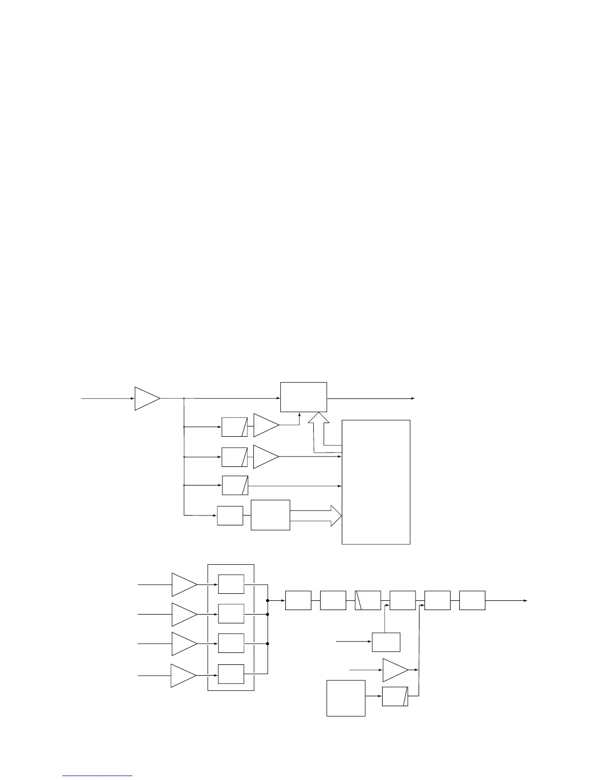
3-1-6 RECEIVER MUTE CIRCUITS (LOGIC UNIT)
• NOISE SQUELCH
The noise squelch circuit cuts out AF signals when no RF
signals are received. By detecting noise components in the
AF signals, the squelch circuit switches the AF mute switch.
Some noise components in the AF signals from the FM IF IC
(RX unit; IC2, pin 9) are passed through the SQL level con-
troller (VR unit; R2). The level controlled signals are applied
to the active filter section in the FM IF IC (RX unit; IC2, pin
8). Noise components about 10 kHz are amplified and out-
put from pin 7 (RX unit; IC2).
The filtered signals are converted to the pulse-type signals
at the noise detector section and output from pin 13 (RX
unit; IC2).
The NDET signal from the FM IF IC (RX unit; IC2) is applied
to the CPU (IC33, pin 40). The CPU analyzes the noise con-
dition and controls the AF mute signal via “AFMUTE1” line
(IC40, pin 4) to the AF mute switch (IC16).
• CTCSS AND DTCS
The tone squelch circuit detects AF signals and opens the
squelch only when receiving a signal containing a matching
subaudible tone (CTCSS or DTCS).
The CTCSS signal passes through the low-pass filter circuit
(IC8, pins 1, 3, 5, 7, 8, 10) and is then applied to the CTCSS
decoder IC (IC29). The detected signal is applied to the
CPU (IC33) via the serial signal line.
The DTCS signal passes through the low-pass filter circuit
(IC12), and is then applied to the DTCS decoder which is
inside the CPU (IC33, pin 52) via the “DTCSI” line.
The 2/5TONE signals are pass through the low-pass filter
circuit (IC12), and are then applied to the 2/5TONE decoder
which is inside the CPU (IC33 pin 51) via “25TI” line.
The DTMF signal passes through the DTMF switch IC
(IC30), and is then applied to the DTMF decoder (IC31). The
decoded signal is applied to the CPU (IC33, pins 82, 85, 86).
The CPU analyzes the DTMF signal.
The DTMF switch (IC30) selects the signal from telephone
line or RX unit.
 Loading...


