3 - 3
3-2 TRANSMITTER CIRCUITS
3-2-1 AF AMPLIFIER CIRCUIT (LOGIC UNIT)
• IN CASE OF THE AF SIGNAL FROM THE MIC JACK
The AF signals (MIC) from the MIC jack (FRONT unit; J7)
are amplified at the AF amplifier (IC1). The amplified signals
are mixed with the “E_MOD”, “E_MOD2” and “TELAFO” sig-
nals from IC1. The mixed signals pass though the high-pass
filter (IC2, pins 1, 2, 6, 7) via the pre-emphasis circuit (IC2,
pins 8, 9).
The filtered signals are applied to the limiter amplifier(IC3),
and are then mixed with the DTMF signal from the CPU
(IC33, pin 43) via the TX-signal filter (IC3). The mixed sig-
nals are applied to the splatter filter (IC4), and are then
applied to the TX unit.
• IN CASE OF THE AF SIGNAL FROM THE ANTENNA
CONNECTOR
The AF signals (received signals) from the antenna connec-
tor (RX unit; J1) are applied to the buffer amplifier (IC9),
CTCSS detector (IC29) and AF amplifier (IC6). The ampli-
fied signals are applied to the D/A converter IC (IC25, pins
8, 9) to adjust to repeater AF level. The adjusted AF signals
pass through the RPT AF mute switch (IC14), and are
applied to the limiter amplifier (IC3).
• IN CASE OF THE 2/5TONE SIGNALS
The 2/5TONE signals from the CPU (IC33, pin 43) are
applied to the mixer amplifier (IC3) via TX signal filter circuit
(IC3, pins 8, 10, 12, 14).
• IN CASE OF THE DTMF SIGNALS
The DTMF signals from dialler IC (IC47, pin 14) are applied
to the mixer amplifier (IC3) via the TX signal filter circuit
(IC3).
• IN CASE OF THE CTCSS AND DTCS SIGNALS
The CTCSS and DTCS signals from the CPU (IC33, pin 44)
are applied to the TX-tone filter (IC4, pins 12, 14). The fil-
tered signals are applied to the converter IC (TX unit; IC5) to
adjust tone level, and are then mixed with AF signal at the
mixer amplifier IC (TX unit; IC6).
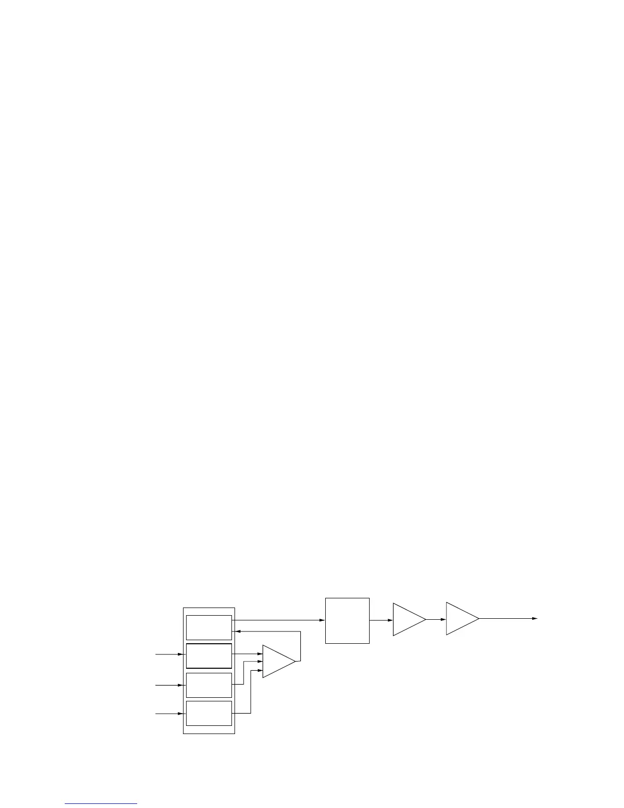
3-2-2 MODULATION CIRCUIT (TX UNIT)
The modulation circuit modulates the VCO oscillating signal
(RF signal) using the AF signals.
The filtered signals from the LOGIC unit are applied to the
D/A converter (IC5, pin 4) to adjust AF level. The adjusted
signals are applied to the mixer amplifier IC (IC6, pin 1) with
the CTCSS/DTCS signals.
The CTCSS/DTCS signals from the CPU (LOGIC unit; IC33,
pin 44) pass through the TX-tone filter (LOGIC unit; IC4),
and are then applied to the D/A converter (IC5 pin9) to
adjust tone level.
The mixed signals are applied to the TX VCO circuit to mod-
ulate the oscillated signal (TVCO unit; D5). The TVCO out-
put is amplified at the buffer amplifiers (Q1, Q2), and is then
applied to the drive amplifier circuit on the 50PA (IC-FR4100;
25PA) unit.
3-2-3 DRIVE AMPLIFIER CIRCUIT
The drive amplifier circuit amplifies the VCO oscillating sig-
nal to the level needed at the power amplifier.
• IC-FR4000 (50PA UNIT)
The RF signal from the TX unit pass through the attenuator
circuit (R12–R14), the low-pass filter circuit (L1, L13, C3,
C4), and is then applied to the YGR amplifier (Q1). The
amplified signal passes through the low-pass filter circuit
(L4, L5, C8, C9, C56, C66), the attenuator circuit (R3–R5),
and is then applied to the pre-drive amplifier IC1.
• IC-FR4100 (25PA UNIT)
The RF signal from the TX unit pass through the low-pass
filter circuit (L19, L22, C112, C60), is applied to the pre-drive
(Q4) to amplify the level needed at the power amplifier (IC2).
The amplified signal passes through the low-pass filter cir-
cuit (L23, L24, C113–C116), the attenuator circuit (R29,
R31, R32), and is then applied to the power amplifier (IC2).
 Loading...


