5 - 1
5-1 PREPARATION
‘‘
REQUIRED TEST EQUIPMENT
‘‘
ENTERING ADJUSTMENT MODE
q Turn power OFF.
w Input the square wave (as illustration at page 5-2) to the [SP] jack (RF unit; J2).
e Push and hold the [FUNC] key, and then turn power ON.
NOTE: When turning power OFF disconnecting the square wave, cancelled the adjustment mode.
‘‘
OPERATING ON THE ADJUSTMENT MODE
Change the adjustment item or channel : [Ω] or [≈]
Change the value : [DIAL]
‘‘
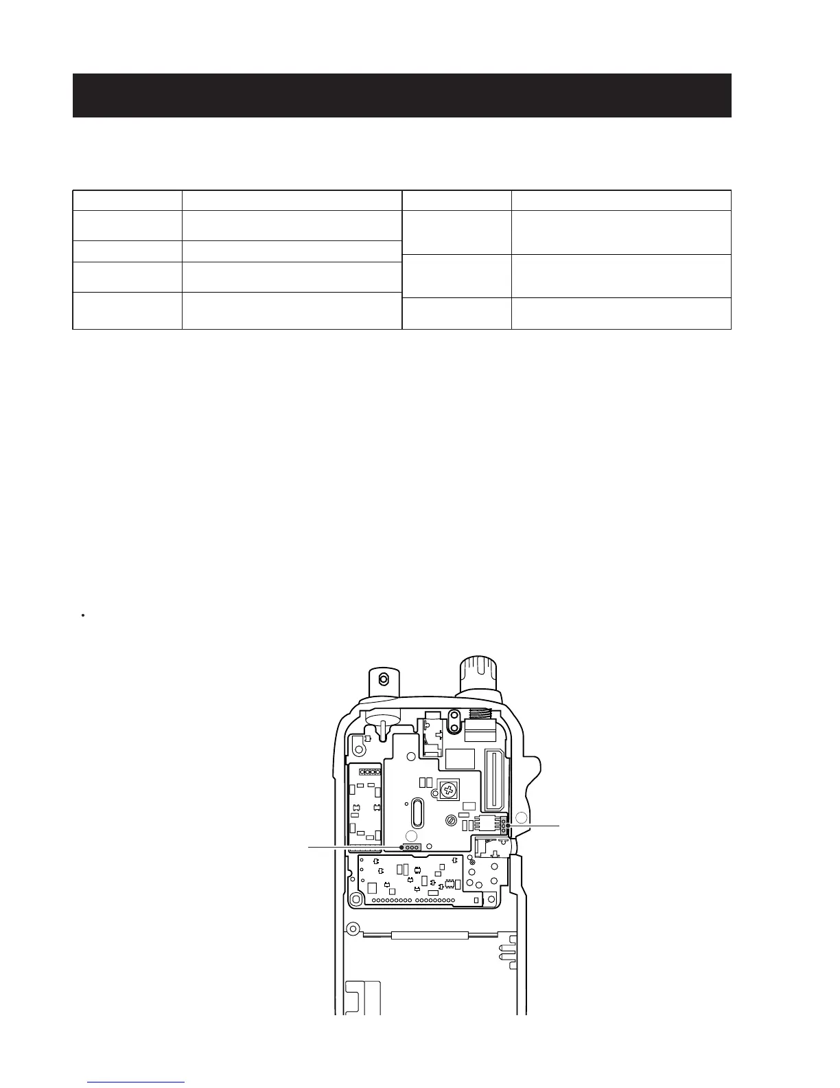
FM-TV FREQUENCY ADJUSTMENT ([OTH-2] ONLY)
When adjusting “FM-TV FREQUENCY”, need to remove the FM-TV unit from the IC-R3 as follow.
q Unsoldering 3 points A and 3 points B.
w Pull up the FM-TV unit.
EQUIPMENT
DC power supply
Digital multimeter
Oscilloscope
Audio generator
GRADE AND RANGE
Output voltage : 4.5 V DC
Current capacity : 1 A or more
Input impedance : 10 MΩ/DC or better
Frequency range : DC–20 MHz
Measuring range : 0.01–10 V
Frequency range : 1–3000 Hz
Measuring range : 0.01–10 V
EQUIPMENT
Frequency counter
Standard signal
generator (SSG)
Digital DC voltmeter
GRADE AND RANGE
Frequency range : 0.1–2500 MHz
Frequency accuracy : ±1 ppm or better
Sensitivity : 100 mV or better
Frequency range : 0.1–2500 MHz
Output level : 0.1 µV–32 mV
(–127 to –17 dBm)
Input impedance : 10 MΩ/DC or better
SECTION 5 ADJUSTMENT PROCEDURES
 Loading...