5 - 7
5-4 TFT LCD AND FM-TV UNIT ADJUSTMENTS
LCD LIGHT
ON
DC-DC
VOLTAGE
VIDEO
SYNCHRO-
NOUS
OSD
FREQUENCY
FM-TV
FREQUENCY
([OTH-2] only)
ADJUSTMENT
ADJUSTMENT ADJUSTMENT CONDITION
MEASUREMENT
VALUE
POINT
UNIT LOCATION UNIT ADJUST
1
1
1
1
1
• Displayed frequency :
2 channel
• Mode :
TV mode
• Push and hold [FUNC] key, and
then push [Y] or [Z] key.
• Displayed frequency :
2 channel
• Mode :
TV mode
• Receiving
• Displayed frequency :
2 channel
• Mode :
TV mode
• Receiving
• Displayed frequency :
2 channel
• Mode :
TV mode
• Receiving
• Remove the FM-TV unit.
• Solder CP2 to short the junction
point (as shown next page).
• Connect a 5 V power supply to
the [FMTV5] terminal (J1, pin 2)
• Connect an SSG to the [IFIN] ter-
minal on the PCB and set as :
Frequency : 426.05 MHz
Level : 1 mV
* (–47 dBm)
Modulation : OFF
• Receiving
Front
panel
LOGIC
LOGIC
Front
panel
FM-TV
Display
Connect the digital
voltmeter to the
check point 5V.
Connect the oscillo-
scope to the check
point CP1.
Display
Connect the digital
voltmeter to the
CP2.
The LCD lights ON
5.1 V
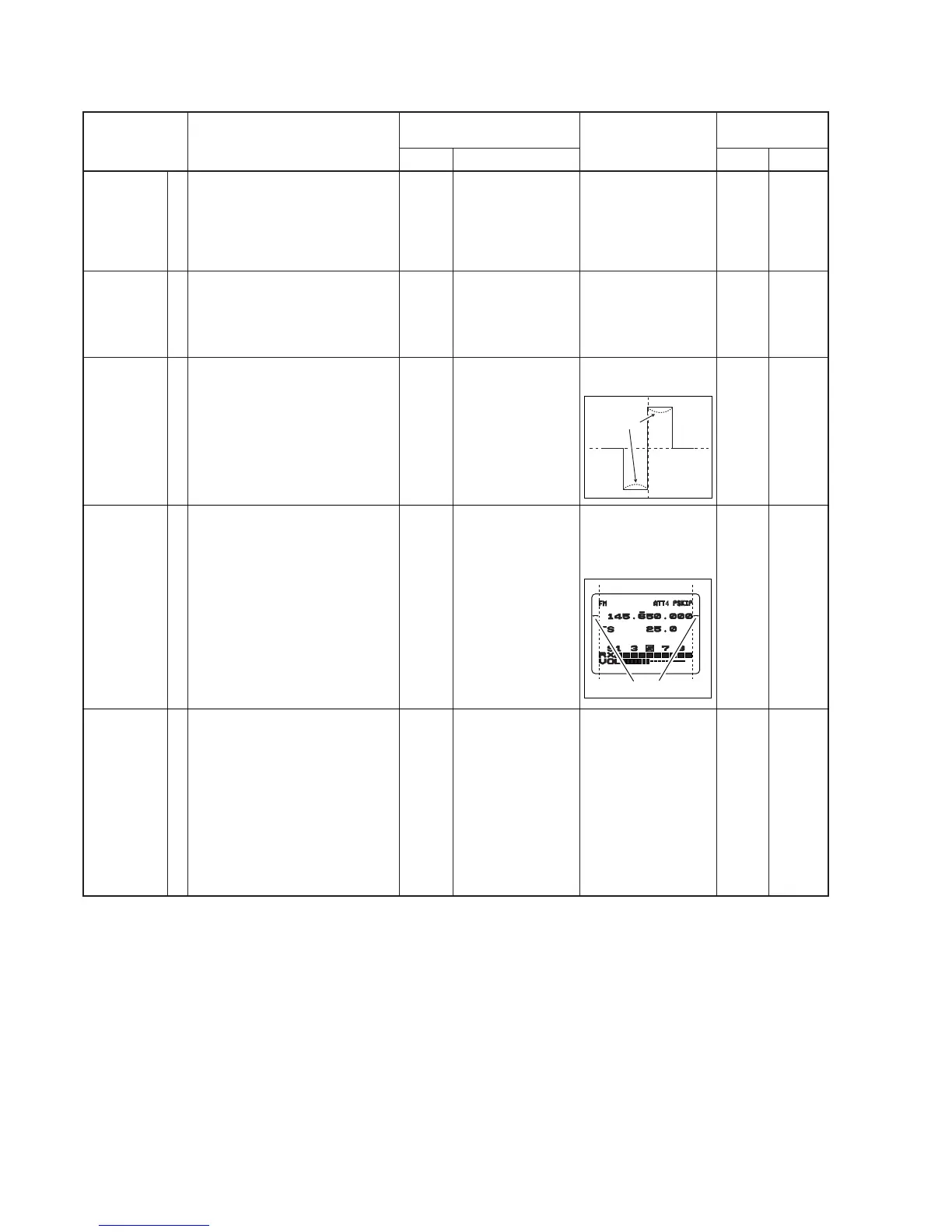
Set the waveform as
below
Set the same space
both left side and right
side on the display as
below
1.5 V
LOGIC
LOGIC
LOGIC
FM-TV
Verify
R805
R902
C935
L2
*This output level of the standard signal generator (SSG) is indicated as SSG’s open circuit.
 Loading...