3 - 2
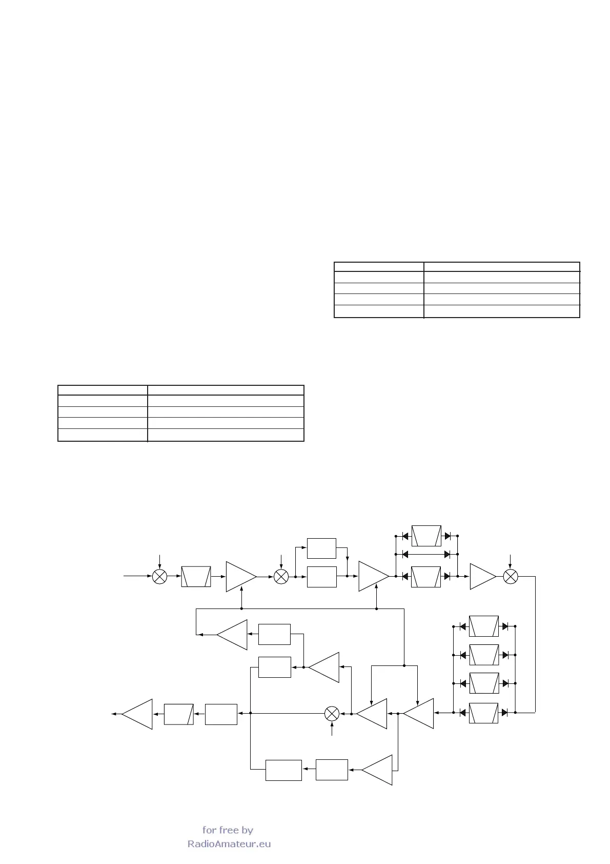
3-1-3 PRE-AMPLIFIER CIRCUIT (MAIN UNIT)
The pre-amplifier circuit uses low noise junction FETs (Q381,
Q382) or wideband amplifier (IC391) to provide gain over a
wide frequency range.
When the [P.AMP] switch is turned “PREAMP 1”, the signals
from the RF filter are amplified by the junction FETs pre-
amplifier circuit (Q381, Q382).
When the [P.AMP] switch is turned “PREAMP 2”, the signals
from the RF filter are amplified by the wideband pre-amplifi-
er circuit (IC391).
When the [P.AMP] switch is turned “PREAMP OFF”, the sig-
nals from the RF filter bypass the pre-amplifiers through
D371 and D372.
The amplified or bypassed signals are applied to the 1st
mixer circuit (Q441, Q442) via the low-pass filter (L431, L432
and C431–CC436). The low-pass filter attenuates at 50 MHz
to suppress image frequency.
3-1-4 1ST MIXER AND IF CIRCUITS (MAIN UNIT)
The filtered signals are mixed with a 69.0415–129.0115 MHz
1st LO signal to produce a 69.01 MHz 1st IF signal at the 1st
mixer circuit (Q441, Q442).
The 1st mixer circuit employs a balanced mixer using low-
noise junction FETs (Q441, Q442) to expand the dynamic
range.
The 69.0415–129.0115 MHz 1st LO signal is applied to an
LO amplifier (Q411) from the PLL unit via J411, and then
passes through the low-pass filter (L421, L422, C422–C425).
The filtered signal is applied to the 1st mixer circuit.
The 1st IF signal is applied to the crystal bandpass filter(FI-
461) to suppress out-of-band signals. The filtered signal is
amplified at a 1st IF amplifier (Q471), and then applied to a
2nd mixer circuit (D491)
3-1-5 2ND MIXER AND IF CIRCUITS (MAIN UNIT)
The 1st IF signal is mixed with a 60.0 MHz 2nd LO signal to
produce 9 MHz 2nd IF signal at the 2nd mixer (D491, C492,
L491, L492). The 60.0 MHz 2nd LO signal is applied to the
2nd mixer from the PLL unit via J491.
The 9 MHz 2nd IF signal is applied to the crystal bandpass
filter (FI701) to suppress unwanted signals.
The filtered signal enters the noise blanker gate
(D711–D714). The signal is applied to L712 to obtain clear
reception and is then amplified at the 2nd IF amplifier (Q721).
The signal passes through a loose resonator circuit (C726,
L721) and then is applied to one of the two crystal bandpass
filters.
MODE
LSB, USB, FM
CW
RTTY
AM, S-AM
FREQUENCY
69.0115 MHz
69.0106 MHz
69.0105 MHz
69.0100 MHz
1ST IF FREQUENCY
 Loading...