5
1
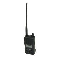
PANEL DESCRIPTION
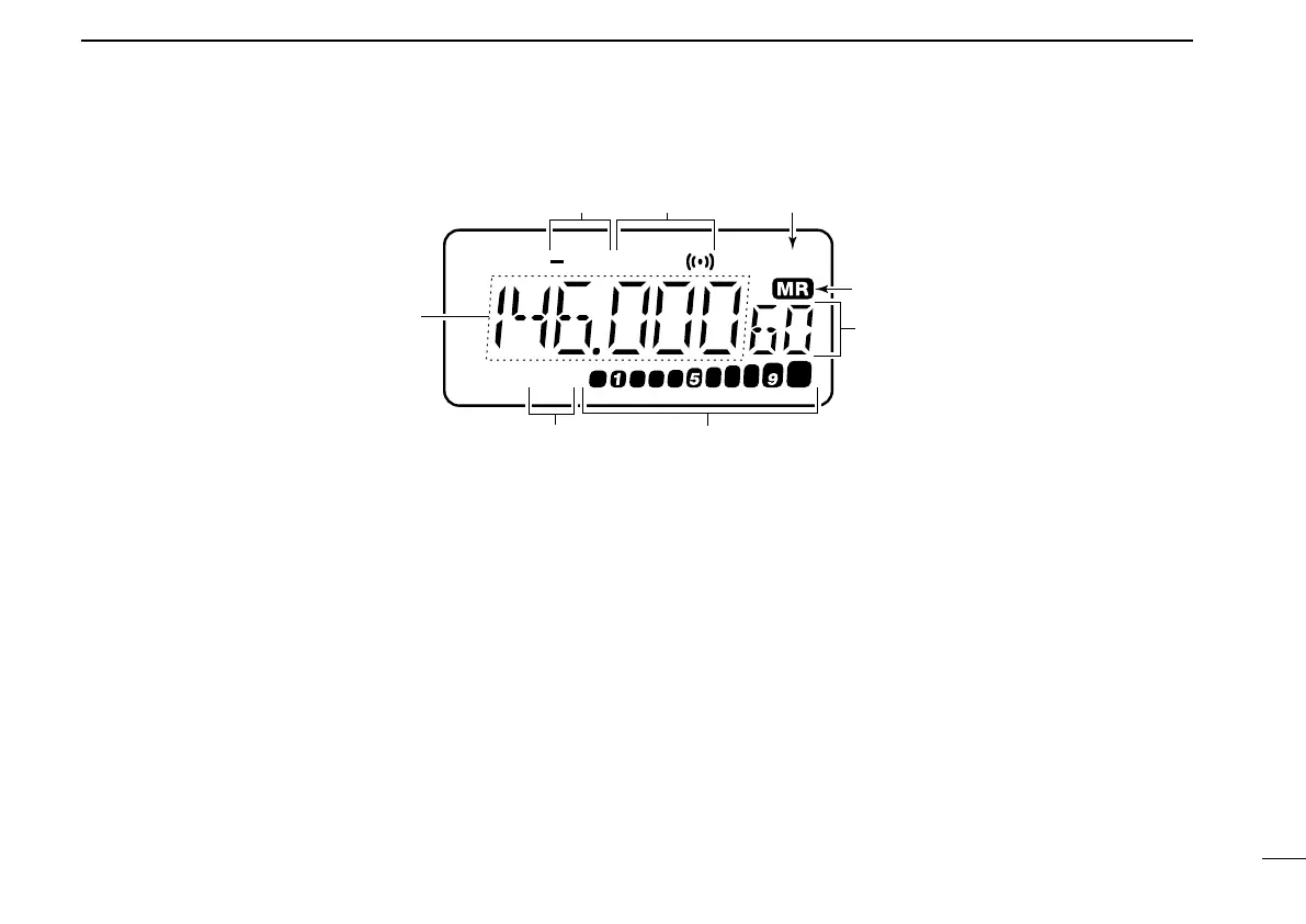
t MEMORY CHANNEL INDICATOR (p. 12)
Indicates the selected memory channel and other items
such as the call channel, key lock indicator, etc.
y S/RF INDICATORS (p. 12)
Show the relative signal strength while receiving.
and the output power selection while transmitting.
u LOW POWER INDICATOR (p. 12)
Appears when low output power is selected.
i ALPHANUMERIC READOUTS
Show the selected frequency, set mode contents, etc.
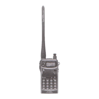
D
LOW
UP T SQL SKIP
qw e
r
t
yu
i
■ Function display
q DUPLEX INDICATORS (p. 13)
Appear during semi-duplex operation.
• “– DUP” appears for minus duplex; “DUP” only appears for plus
duplex.
w TONE INDICATORS (p. 21)
“T” appears when the subaudible tone encoder is in use,
“T SQLS” appears during pocket beep operation and
“T SQL” appears when the tone squelch function is acti-
vated.
e SKIP INDICATOR (p. 20)
Appears when a selected memory channel is set as a skip
channel.
r MEMORY MODE INDICATOR (p. 15)
Appears while in memory mode.
IC-T7H-2.qxd 2007.07.19 4:10 PM Page 5
 Loading...