4 - 4
• RADIO RECEIVE CIRCUITS
IC2
VO-
VO+
IC11
IC25
MAIN UNIT
LOGIC UNIT
CHASSIS UNIT
[SP] jack
-Band A:FM/FM-N mode-
-Band A:DV mode-
-Band A:FM/AM mode-
Radio AF
AF
IC350,Q350
FIL
SW
MUTE
BAF
CODEC
LINEAR
IC18
DSP
IC19
ADET
BDET
Q20
IC351
IC20
FIL
SW
MODE
AF
IC300,Q301
IC390
AAF
From the
2nd IF circuit
(Band A).
From the
2nd IF circuit
(Band B).
IC300
IC300
Q302,Q300
AF
AMP
J4
SP1
Int. speaker
A/D
LPF
BUFF
ATT
AMP
LPFAMP
DAFO
D/A
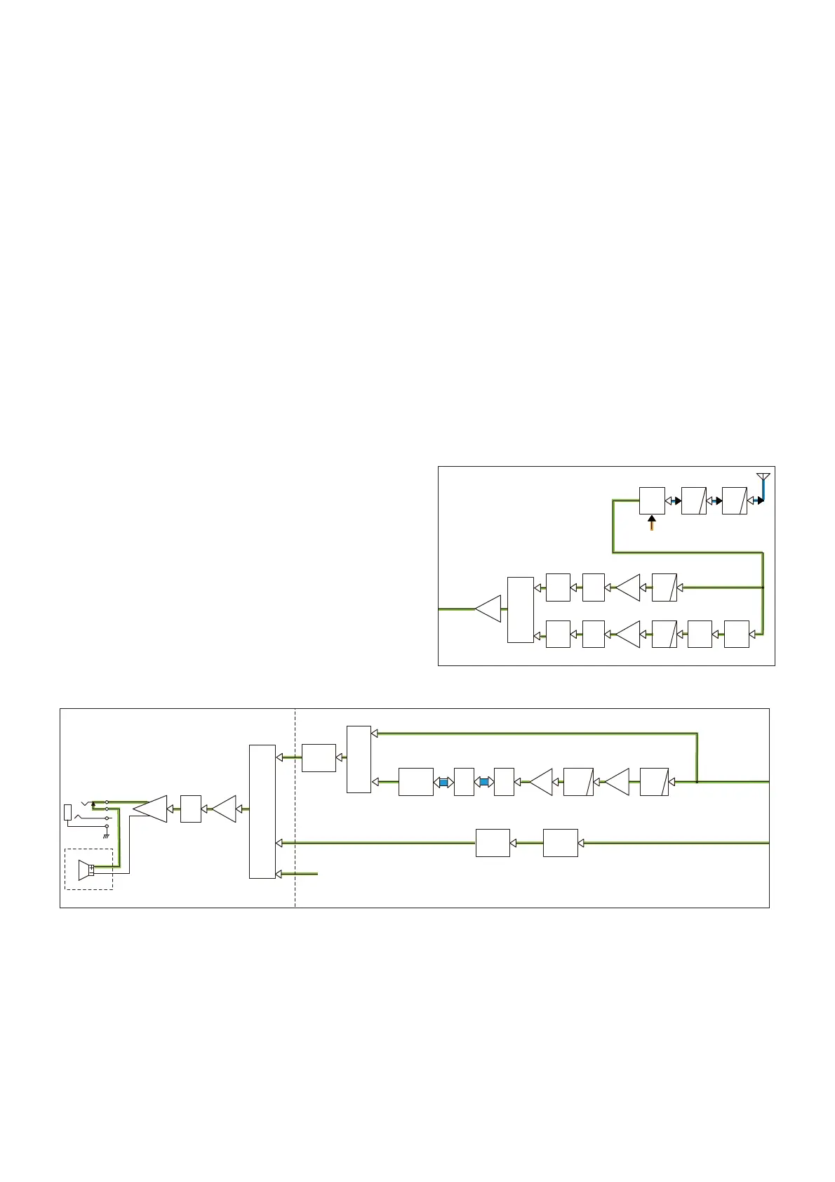
• DIGITAL DEMODULATION AND RX AF CIRCUITS
DIGITAL DEMODULATION CIRCUIT (LOGIC UNIT)
While operating in the DV mode, the demodulated signal
(digital audio signal) is passed through the LPF (R305, R336,
R339, C334 and C337) and amplifi ed by the AF AMP (IC300,
pins 2 and 1). The amplifi ed signal is passed through the LPF
(Q300 and Q302) and amplifi ed by another AF AMP (IC300,
pins 13 and 14), and then applied to the A/D converter (IC19,
pin 3) to be converted into the digital audio signal.
The digital audio signal is demodulated by the DSP (IC18,
pins M10 and L11), and then applied to the linear codec
(IC25) to be decoded into an analog audio signal.
The decoded AF signal is applied to the RX AF circuit.
RX AF CIRCUIT (LOGIC AND MAIN UNITS)
• Band A
The demodulated AF signal is passed through the mode SW
(IC390, pins 4 and 3) and AF fi lter (IC300, pins 9 and 8, 5
and 7), and then applied to the D/A converter (MAIN UNIT:
IC11, pin 18) to be adjusted in volume level.
• Band B
The demodulated AF signal is passed through the AF fi lter
(IC350, pins 2 and 1, 5 and 7) and mute SW (IC351, pins 2
and 1), and then applied to the D/A converter (MAIN UNIT:
IC11, pin 1) to be adjusted in volume level.
The level-adjusted AF signal is amplifi ed by the buffer (MAIN
UNIT: IC20, pins 3 and 4), and then applied to the AF power
AMP (MAIN UNIT: IC2, pin 1), through the ATT (MAIN UNIT:
Q20).
The amplifi ed AF signal is output to the internal speaker
(CHASSIS: SP1) or external speaker, through the [SP] jack
(MAIN UNIT: J4).
RADIO RECEIVE CIRCUITS
• FM BAND (76–108 MHz)
The RF signal from the antenna or earphone is passed through
two LPFs (L513, L515, L516, C547, C549, C553, C555 and
C556), ANT SW (D506 and D903), RF SW (D781), ANT SW
(D782 and D783) and LPF (L781, L782, C783 to C786), and
then applied to the RF AMP (Q780).
The amplifi ed signal is applied to the radio IC (IC441, pin 2),
through the ATT (D908) and limiter (D904).
• AM BAND (0.52–1.71 MHz)
The RF signal from the antenna is passed through two LPFs
(L513, L515, L516, C547, C549, C553, C555 and C556),
ANT SW (D506 and D903), and LPF (L402, L403, C407–
C411), and then applied to the RF AMP (Q908).
The amplifi ed signal is applied to the radio IC (IC441, pin 4),
through the ATT (Q906 and Q907) and limiter (D905).
The radio IC (IC441) demodulates input signals and output to
the RX AF circuit.
D782,
D783
- 76M-108MHz -
Q780
Q908
- 0.52M-1.71MHz -
LIMIT
D905
D904
LIMIT
RADIO
IC
IC441
Q906
Q907
D908 D781
IC955
<- RX AF
circuit
From the TX circuit
LPF
ANT
SW
LPF
LPF
RF
AMP
LPF
RF
AMP
ATT
ATT
RF
SW
ANT
SW
BUFF

 Loading...


