4 - 7
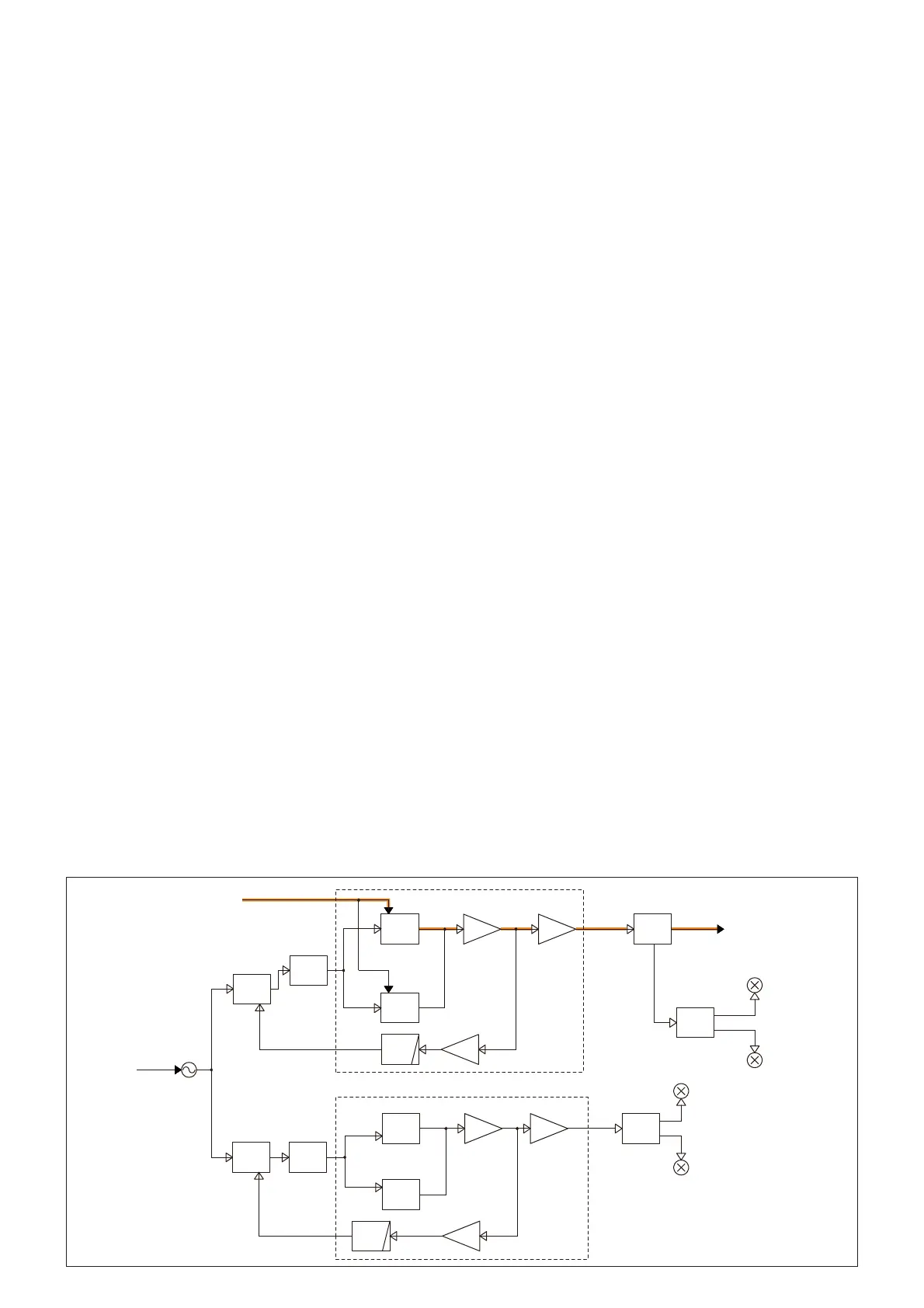
4-3 FREQUENCY SYNTHESIZER CIRCUIT
(MAIN UNIT)
VCOs
The ID-51A/E has total of four VCOs; two VCOs for band A
and another two for band B.
• Band A
VHF VCO (VCO1 UNIT)
The VHF VCO (Q311, D304–D306) generates both 1st LO
signal (for receiving a VHF signal on band A) and the VHF
TX signal. The output of buffer (Q200) is amplifi ed by the LO
AMP (Q201), and then used as the VHF TX/RX LO signal.
While receiving, the LO signal is applied to the 1st IF mixer
(Q820) for receiving a signal on the VHF band, through the
RF SW (D821).
While transmitting, the LO signal is applied to the TX AMP
circuits, through the LO SW (D14).
UHF VCO (VCO1 UNIT)
The UHF VCO (Q27, D10–D12) generates both 1st LO signal
(for receiving a UHF signal on band A) and the UHF TX sig-
nal. The output of buffer (Q200) is amplifi ed by the LO AMP
(Q201), and then used as the UHF TX/RX LO signal.
While receiving, the LO signal is applied to the 1st IF mixer
(Q801) for receiving a signal on the UHF band, through the
RF SW (D802).
While transmitting, the LO signal is applied to the TX AMP
circuits, through the LO SW (D14).
• Band B
VHF VCO (VCO2 UNIT)
The VHF VCO (Q311, D304–D306) generates the 1st LO
signal (for receiving a VHF signal on band B). The output of
buffer (Q200) is amplifi ed by the LO AMP (Q201), and then
used as the 1st LO signal.
While receiving, the LO signal is applied to the 1st IF mixer
(MAIN UNIT: Q830) for receiving a signal on the VHF band,
through the RF SW (MAIN UNIT: D831).
UHF VCO (VCO1 UNIT)
The UHF VCO (Q27, D10–D12) generates 1st LO signal
(for receiving a UHF signal on band B). The output of buffer
(Q200) is amplifi ed by the LO AMP (Q201), and then used as
the UHF TX/RX LO signal.
While receiving, the LO signal is applied to the 1st IF mixer
(MAIN UNIT: Q811) for receiving a signal on the UHF band,
through the RF SW (MAIN UNIT: D812).
PLL
•Band A
A portion of VHF and UHF VCOs output signal is amplifi ed
by two buffers (VCO1 UNIT: Q200 and Q202) and passed
through the LPF (VCO1 UNIT: L202, C209 to C211), and
then fed back to the PLL IC (IC6, pin 8).
The PLL IC (IC6) phase-compares the output of reference
frequency oscillator (TCXO; X1) and VCO, and the phase dif-
ference is output as the charge pump current. The current is
passed though the loop fi lter (R67, R71, R90, R93, C91, C92,
C96 and C102) to be converted into the lock voltage, which
controls the oscillating frequency of VCO.
When the oscillation frequency drifts, its phase changes from
that of the reference frequency, causing a lock voltage change
to compensate for the drift in the VCO oscillating frequency.
Band B
A portion of VHF and UHF VCOs output signal is amplifi ed
by two buffers (VCO2 UNIT: Q200 and Q202) and passed
through the LPF (VCO2 UNIT: L202, C209 to C211), and
then fed back to the PLL IC (IC6, pin 8).
The PLL IC (IC6) phase-compares the output of reference
frequency oscillator (TCXO; X1) and VCO, and the phase dif-
ference is output as the charge pump current. The current
is passed though the loop fi lter (R452, R454, R455, R457,
C455, C457 to C460) to be converted into the lock voltage,
which controls the oscillating frequency of VCO.
When the oscillation frequency drifts, its phase changes from
that of the reference frequency, causing a lock voltage change
to compensate for the drift in the VCO oscillating frequency.
FIN
X1
Q202
Q311,
D304,D305,D306
15.3MHz
IC6
Q201
Q200
VCO1 UNIT
VCO2 UNIT
LO
SW
D14
A_LO
TX AMP circuit. ->
B_LO
Q811
Q830
D812,D831
Q801
Q820
VHF 1st LO
UHF 1st LO
VHF 1st LO
UHF 1st LO
REFMOD
Q27,
D10,D11,D12
VHF
UHF
Q202
Q200
Q27,D10,D11,D12
Q201
UHF
VHF
FIN
IC450
Q311,D304,D305,D306
D802,D821
A_LOOUT
LPF
FIL
LOOP
VCO
BUFF
PLL
IC
LO
AMP
RF
SW
RF
SW
VCO
BUFF
PLL
IC
LPF
VCO
VCO
BUFF
AMP
LO
AMP
FIL
LOOP
VCOMOD
• FREQUENCY SYNTHESIZER CIRCUIT