19
- Installation & Servicing
INSTALLATION
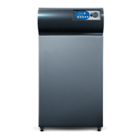
DHW Output Limiting
It is possible to limit the output of the boiler when working in DHW mode. This is in
order to avoid overheating when the DHW storage tank absorbed input is less than the
boiler produced output. To limit the DHW output of the boiler change the DIP switch
settings on the AM-4 board (see Frame 20 for location of AM-4 board). By changing the
DIP switch settings you can exclude 1, 2 or 3 modules from firing in DHW mode, see
table below for settings:
AM-4
0-10 V
DHW
Tank
NTC
DIPSWITCH 1DIPSWITCH 2
X1
X2
21
INTERFACE BOARD - AM4 supplementary Board
Output Reduction -120 kW -80 kW -40 kW None
Dip
Switch
Configuration
Examples of a 1 module 2 modules 3 modules All modules
available available available available
F160 (40 kW) (80 kW) (120 kW) (160 kW)
Examples of a 4 modules 5 modules 6 modules All modules
available available available available
F280 (160 kW) (200 kW) (240 kW) (280 kW)
12
O
F
F
O
N
12
O
F
F
O
N
12
O
F
F
O
N
12
O
F
F
O
N
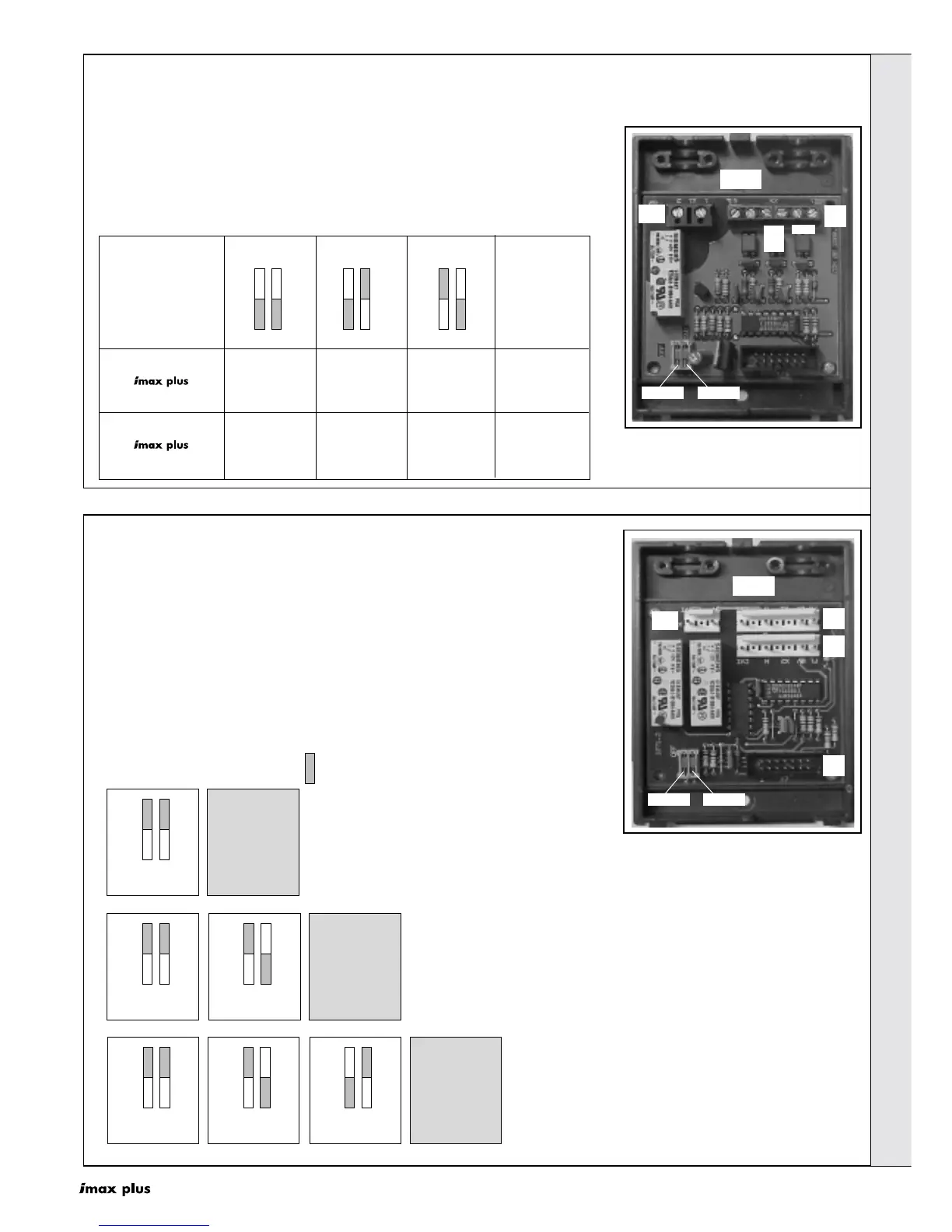
The Modular Boiler Drive (MBD), see Frame 20 for location,
manages to check a two-burner group (2 x 40 = 80 kW). For
boilers with outputs greater than 80 kW, 1, 2 or 3
supplementary AM-5 boards are included, each of them
managing to check up to 2 burners. For example, a boiler with
5 burners (200 kW) is equipped with two supplementary AM-5
boards.
The supplementary boards have two small dip-switches,
which must be positioned according to the diagram shown
below. The setting operation is carried out during manufacture
and must also be done on site in case of service replacement.
22
INTERFACE BOARD - AM5 Supplementary Board
Thermal Element
AM-5 N.1
AM-4
12
O
F
F
O
N
Thermal Element
AM-5 N.2
AM-4
12
O
F
F
O
N
Thermal Element
AM-5 N.1
12
O
F
F
O
N
Thermal Element
AM-5 N.3
AM-4
12
O
F
F
O
N
Thermal Element
AM-5 N.2
12
O
F
F
O
N
Thermal Element
AM-5 N.1
AM-5 SUPPLEMENTARY BOARD
AM-5 and AM-4 boards positioning for a MODULEX 120 or 160
POSITION OF DIPSWITCHES
AM-5 and AM-4 boards positioning for a MODULEX 200 or 240.
AM-5 and AM-4 boards positioning for a MODULEX 280.
AM-5
DIPSWITCH 1DIPSWITCH 2
X3
X1
X2
X7
POSITION OF DIPSWITCHES
INSTALLATION
 Loading...