31
- Installation & Servicing
INSTALLATION
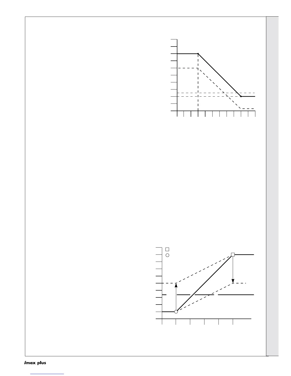
3. BMS Control
When controlling the boiler with a BMS the set flow
temperature is controlled by a 0-10V D.C. signal. The
relationship between the signal voltage and the set flow
temperature (heating curve) is given in graph 5.
The heating curve can be adjusted using the following
parameters (see also Frames 26, 28 and 29):
Parameter G: Required set flow temperature at 0V.
Parameter H: Required set flow temperature at 10V.
Parameter 6: If according to the heating curve the
required set flow temperature is lower than
this value (parameter 6), then the call for
heat is blocked and the boiler will not fire.
The burner will switch on when the Global Flow
Temperature (NTC1) is less or equal to the set flow
temperature +5ºC - CH hysteresis (parameter 8 2nd digit).
The heat demand will however be blocked if the set flow
temperature is less or equal to the Blocking CH Flow
Temperature (parameter 6).
The burner will switch off when the Global Flow
Temperature (NTC1) is greater than the set flow
temperature + 5ºC.
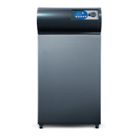
35 HEATING MODE OPERATION CONT'D
2. Outside Sensor with night Time Set Back
With the boiler configured to run with an outside sensor,
there is a permanent call for heat. The set flow temperature
varies with changes in outside temperature (heating curve)
in accordance with graph 4. With a timer connected across
terminals 5 & 6, the set flow temperature is set back by a
fixed amount in response to the circuit being open. This
allows the building temperature to be dropped during
periods e.g. night-time.
The heating curve can be adjusted using the following
parameters (see also Frames 26 and 28):
Parameter 3: Highest set flow temperature required on the
coldest day.
Parameter 4: Lowest set flow temperature required on a
warm day (20ºC).
Parameter 5: The coldest day the heating system is
designed to work against.
Parameter 6: If according to the heating curve the required
set flow temperature is lower than this value
(parameter 6), then the call for heat is
blocked and the boiler will not fire.
Parameter 7: When a timer opens the circuit connected
across terminals 5 & 6, the set flow
temperature is reduced by this value.
Parameter 8: If the outside sensor is not reading the
outside temperature accurately, it is possible
to adjust the reading using this parameter by
+/-5ºC.
The burner will switch on when the Global Flow Temperature
(NTC1) is less or equal to the set flow temperature +5ºC - CH
hysteresis (parameter 8 2nd digit). The burner on will however
be blocked if the set flow temperature is less or equal to the
Blocking CH Flow Temperature (parameter 6).
The burner will switch off when the Global Flow Temperature
(NTC1) is greater than the set flow temperature +5ºC.
100
90
80
70
60
50
40
30
20
10
0
-25 -20 -15 -10 -5 0 5
Outside Temperature (ºC)
Set Flow Temperature (ºC)
10 15 20 25 30
Parameter 5
Parameter 4
Parameter 6
Parameter 7
Parameter 3
ima5793
Graph 4
100
90
80
70
60
50
40
30
20
10
0
0.0 2.5 5.0
DC-Voltage [V]
Set Flow Temperature (ºC)
7.5 10.0
ima5771
settable maximum
settable minimum
Blocking CH
Flow Temperature
(Parameter 6)
Tset at 10V
(Parameter H)
Tset at 0V
(Parameter G)
Graph 5
INSTALLATION
 Loading...