20
- Installation & Servicing
INSTALLATION
23
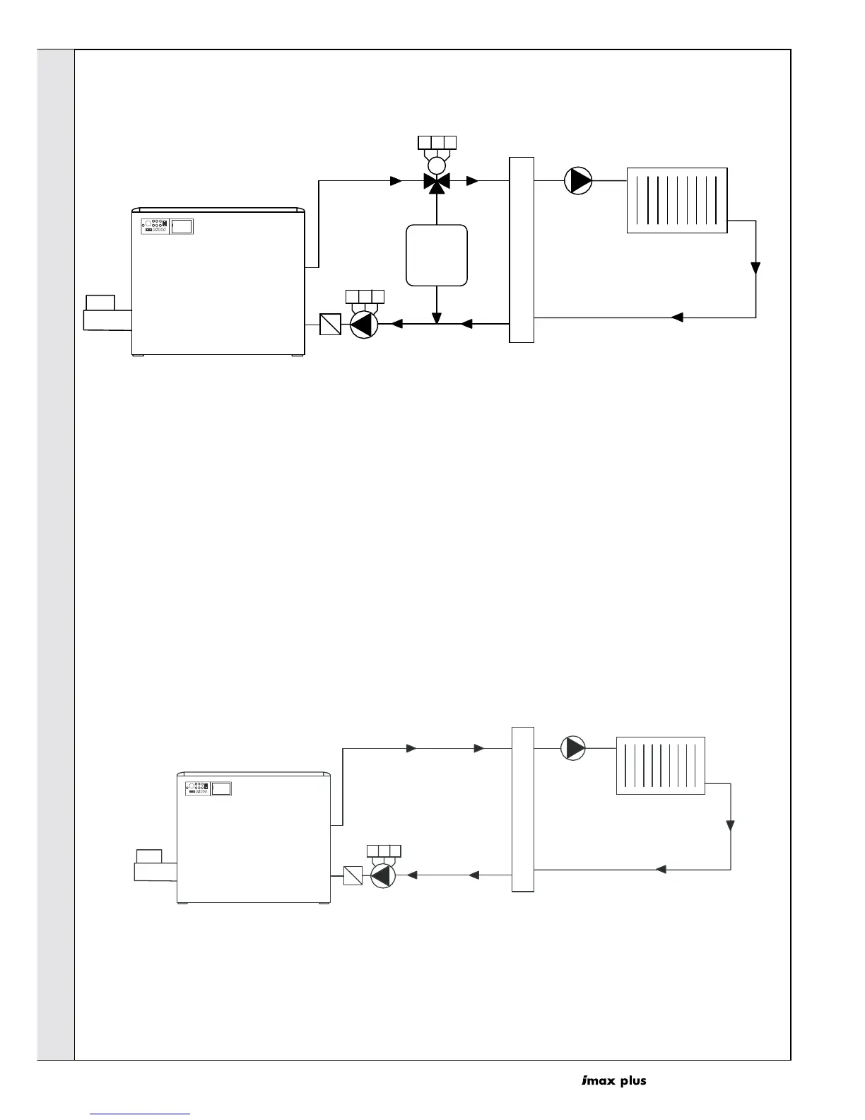
EXAMPLES OF HEATING SYSTEMS
12 43
576
S
T
O
R
E
M
O
D
E
R
E
S
E
T
S
T
E
P
11 12 13
16 17 18
Flow
Return
Primary
System
Pump
Filter
Mixing
Header
Heating circuit
Heating
System
Pump
ima 5781
Storage
tank output
=
boiler output
A
B
AB
3 way diverting valve
M
Heating system with DHW production (storage tank Output = Boiler Output) and mixing
header.
Note.
If PARA 'A' 2nd digit is set to 0, it means you wish to have a 3
way valve normally open towards the CH circuit (radiator
circuits from AB to A). Upon DHW request, terminal 11 is
energised which, through a relay, powers the 3-way valve,
thus closing port A and opening port B. Simultaneously
terminal 16 is energised which, through another relay, powers
the primary system pump.
If PARA 'A' 2nd digit is set to 2, it means you wish to have a 3 way
valve normally open towards the storage tank (DHW circuit from
AB to B). Upon CH request, terminal 11 is energised which,
through a relay, powers the 3-way valve, thus closing port B and
opening port A. Simultaneously terminal 16 is energised which,
through another relay, powers the primary system pump.
12 43
576
S
T
O
R
E
M
O
D
E
R
E
S
E
T
S
T
E
P
11 12 13
Flow
Return
Primary
System
Pump
Filter
Mixing
Header
Heating circuit
Heating
System
Pump
ima 5780
Heating System with one Group of Radiators (controlled by thermostatic valves)
INSTALLATION
 Loading...