26
- Installation & Servicing
INSTALLATION
29
PARAMETER MODE CONT'D
1st Digit - CH type
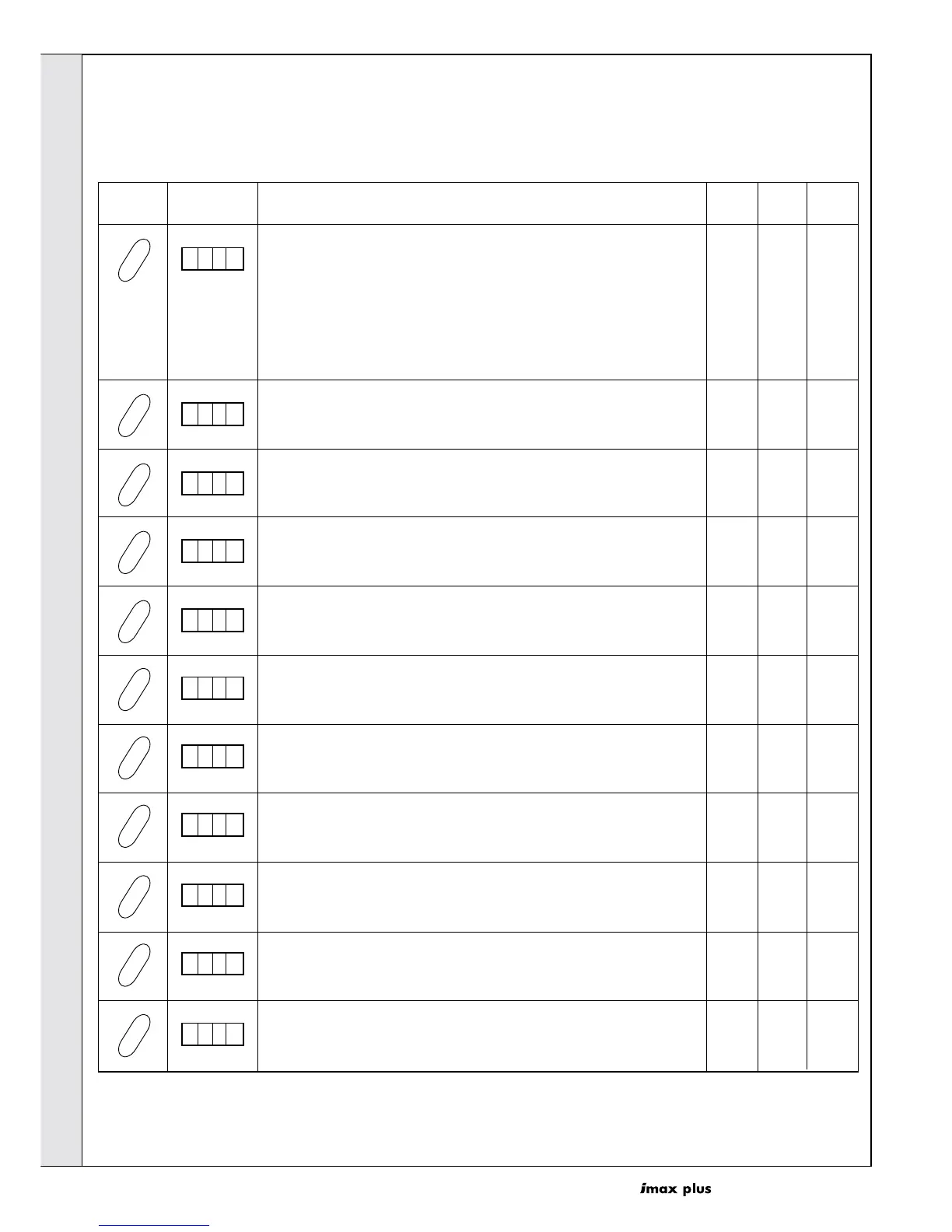
Press Display Description
STEP
Lower
Limit
Upper
Limit
Factory
Setting
01
A. 0 1
0x = Timer/Thermostat with optional weather compensation
1x = Outside Sensor with Night Time Set back
2x = BMS 0-10V Control
DHW set value increase (degC)
STEP
52520
B. 2 0
Temperature added to parameter 1 (see Frame 28) for boiler flow
temperature required to satisfy DHW demand
Maximum fan speed CH (hundreds rpm)
STEP
DO
NOT
ADJUST
C. 2 0
Maximum fan speed DHW (hundreds rpm)
STEP
D. 2 0
Minimum fan speed (hundreds rpm)
STEP
E. 2 0
Ignition fan speed (% of parameter C)
STEP
F. 2 0
2nd Digit - DHW type
x0 = 3-way valve normally open to CH system
x1 = DHW pump
x2 = 3-way valve normally open to DHW tank
DO
NOT
ADJUST
58
DO
NOT
ADJUST
DO
NOT
ADJUST
58
DO
NOT
ADJUST
DO
NOT
ADJUST
22
DO
NOT
ADJUST
DO
NOT
ADJUST
75
Flow temperature set point at 0V (degC)
STEP
G. 2 0
50030
Flow temperature set point at 10V (degC)
STEP
H. 2 0
9050 80
1st digit - Number of module lockouts required to close alarm contacts
STEP
J. 2 0
7x1x
DHW hysteresis (degC)
STEP
L. 2 0
14505
1st digit - Burner System
STEP
N. 2 0
DO
NOT
ADJUST
DO
NOT
ADJUST
0x
x2 to x7
When using 0-10V BMS
When using 0-10V BMS
2nd digit - DHW pump overrun time (30 second increments)
x9x0
2nd digit - Number of Modules
0x = Ideal normal setup
2x to 7x
x1
INSTALLATION
 Loading...