2
OPEN VENT SYSTEM REQUIREMENTS
3
SCHEMATIC PIPEWORK AND SYSTEM BALANCING
The boiler does not normally need a bypass but at least some
radiators on the heating circuit, of load at least 10% of the
minimum boiler output, must be provided with twin lockshield
valves so that this minimum heating load is always available (see
footnote re. thermostatic radiator valves).
connections
load 30 - 60 = 22 mm
load 70 - 80 = 28 mm
Balancing
1. Set the programmer to ON for both CH and HW.
Turn the cylinder thermostat down. Close the
manual or thermostatic valves on all radiators,
leaving the twin lockshield valves (on the radiators
referred to above) in the open position. Turn up the
room thermostat and adjust these lockshield valves
to give boiler ow and return temperatures not more
than 20
o
C apart. These valves should now be left
as set.
2. Open all manual or thermostatic radiator valves and
adjust the lockshield valves on remaining radiators
to give around 20
o
C temperature drop at each
radiator.
3. Turn up the cylinder thermostat and adjust the
cylinder balancing valve so that the cylinder
achieves a maximum ow consistent with adequate
ow to the radiators. Check that with only the
domestic hot water loop in circuit a differential
temperature of 25
o
C across the boiler is not
exceeded.
4. Adjust room and cylinder thermostats and
programmer to NORMAL settings.
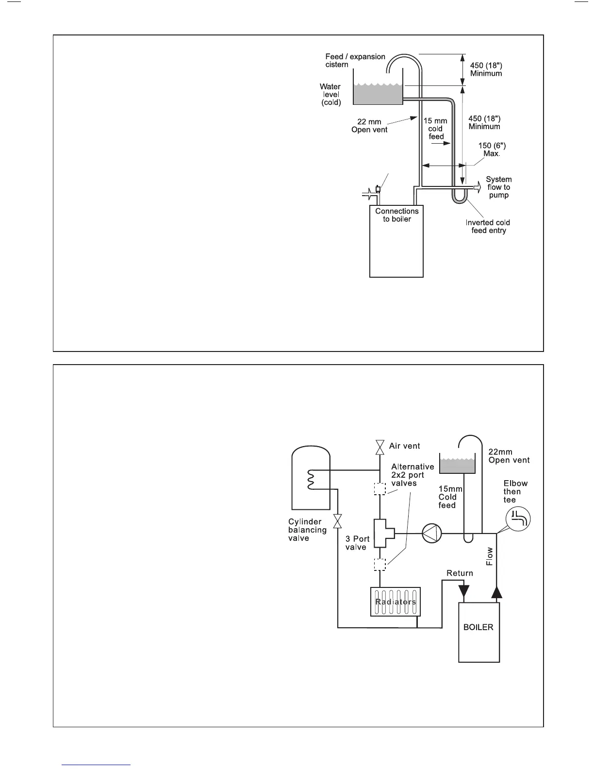
The system should be vented directly off the boiler ow pipe, as
close to the boiler as possible. The cold feed entry should be
inverted and MUST be positioned between the pump and the vent,
and not more than 150mm (6”) away from the vent connection.
Note. Combined feed and vent pipes may also be tted.
There should be a minimum height 450mm (18”) of open vent above
the cistern water level. If this is not possible refer to
Frame 5. The vertical distance between the highest point of the
system and the feed/expansion cistern water level MUST not be
less than 450 mm (18”). The pump must be tted on the ow side of
the boiler.
A suitable pump is a domestic circulator capable of providing a maximum
20
o
C temperature differential across the boiler with the whole of the
heating circuit open (e.g. Grundfos UPS 15/50, 15/60 or equivalent). With
the minimum ow circuit allowed by the controls the differential must not
exceed 25
o
C.
The vertical distance between the pump and feed/expansion cistern
MUST comply with the pump manufacturer’s minimum requirements, to
avoid cavitation. Should these conditions not apply either lower the pump
position or raise the cistern above the minimum requirement specied by
Ideal Stelrad Group. The isolation valves should be tted as close to the
pump as possible.
It is recommended that an automatic air vent should be tted to the return
connection.
 Loading...


