19
DETERMINING THE FLUE LENGTH AND FLUE PACKS REQUIRED........CONT’D
(Equivalent ue length resistance = 1M)
- (Equivalent ue length resistance = 0.6M)
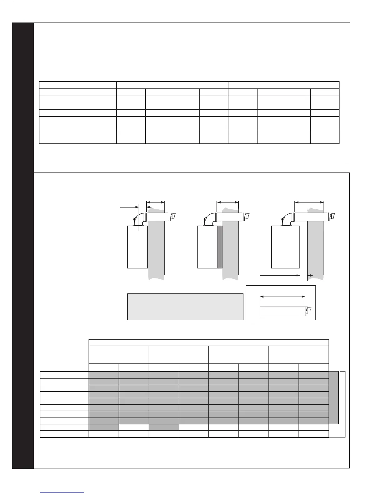
Minimum Horizontal Flue Lengths (Centre line of turret to outside of wall terminal)
Telescopic Flue ‘B’ Pack = 400mm
Horizontal Flue terminal (600mm long) ‘B’ Pack = 285mm
Wall Thickness Std Metric Brick 102.5mm wide
‘B’ Pack Flue Type 60/100 Minimum permissible Wall Thickness Maximum permissible Wall Thickness
Rear Flue Rear Flue + Std-Off Side Flue Rear Flue Rear Flue + Std-Off Side Flue
Horizontal Flue Terminal
(600mm long) B Pack
116 102.5 102.5 501 456 456
Telescopic Flue B Pack 231 186 186 429 384 384
Horizontal Flue Terminal
(1000mm long) B Pack
546 501 501 761 716 716
Horizontal Flue Terminal
(1000mm long) B Pack cut 75mm
471 426 426 686 641 641
For Flue lengths between 658 & 708 use a Horizontal Flue Terminal (1000mm long) B Pack, cut 75mm off the end of the
100mm
to outside face of wall plus
44mm = ue length
Centre of turret to edge of turret = 100mm
Turret has a ue insertion of 30mm
The compressed outer wall seal has protruding wall to seal mounting lip - 14mm
From centreline of turret to wall. Rear mount 155mm, side (including clearance) 200mm
NOTES
REAR
Fit
to wall
A
WALL
to outside face of wall plus
44mm = ue length
SIDE
Fit
to wall
A
WALL
Minimum clearance 5mm
20
DETERMINING THE FLUE LENGTH AND FLUE PACKS REQUIRED, CONT’D
Shows the ue required when measured from outside edge of turret to the outside face of the wall (to obtain cut length add 44mm)
Horizontal Flue Terminal
(600mm long) B Pack
Telescopic Flue B Pack Horizontal Flue
Terminal (1000mm long)
B Pack (Telescopic)
Horizontal Flue Terminal
(1000mm long) B Pack
(Telescopic) Cut 75mm
Minimum Maximum Minimum Maximum Minimum Maximum Minimum Maximum
B Pack (Standard) 171 556 286 484 601 816 526 741
Plus 1 (1m D pack) 1121 1506 1236 1434 1551 1766 1476 1691
Plus 2 (1m D pack) 2071 2456 2186 2384 2501 2716 2426 2641
Plus 3 (1m D pack) 3021 3406 3136 3334 3451 3666 3376 3591
Plus 4 (1m D pack) 3971 4356 4086 4284 4401 4616 4326 4541
Plus 5 (1m D pack) 4921 5306 5036 5234 5351 5566 5276 5491
Plus 6 (1m D pack) 5871 6256 5986 6184 6301 6516 6226 6441
Plus 7 (1m D pack) 6821 7206 6936 7134 7251 7466 7176 7391
Plus 8 (1m D pack) 7771 8156 7886 8084 8201 8416 8126 8341
Plus 9 (1m D pack) 8721 9000 8836 9000 9000 9000 9000 9000
Max output 30 kW
Max output 12,15,18,24 kW
FIGURE 1
FIGURE 2
Note. Maximum permissible
ue length is measured from
centre line of appliance ue
outlet to outside wall face.
Note; Telescopic ue B Pack or attached “D” pack extensions do not need to be cut between minimum and maximum values shown above (except
where specied). Horizontal Flue Terminal (600mm long) B Pack ue will require cutting on values below maximum values shown in the table above.
If using the 2000mm D Pack , the maximum usable length per extension is 1950mm
If using the 500mm D Pack, the maximum usable length per extension is 450mm.
 Loading...


