34
CONNECTIONS
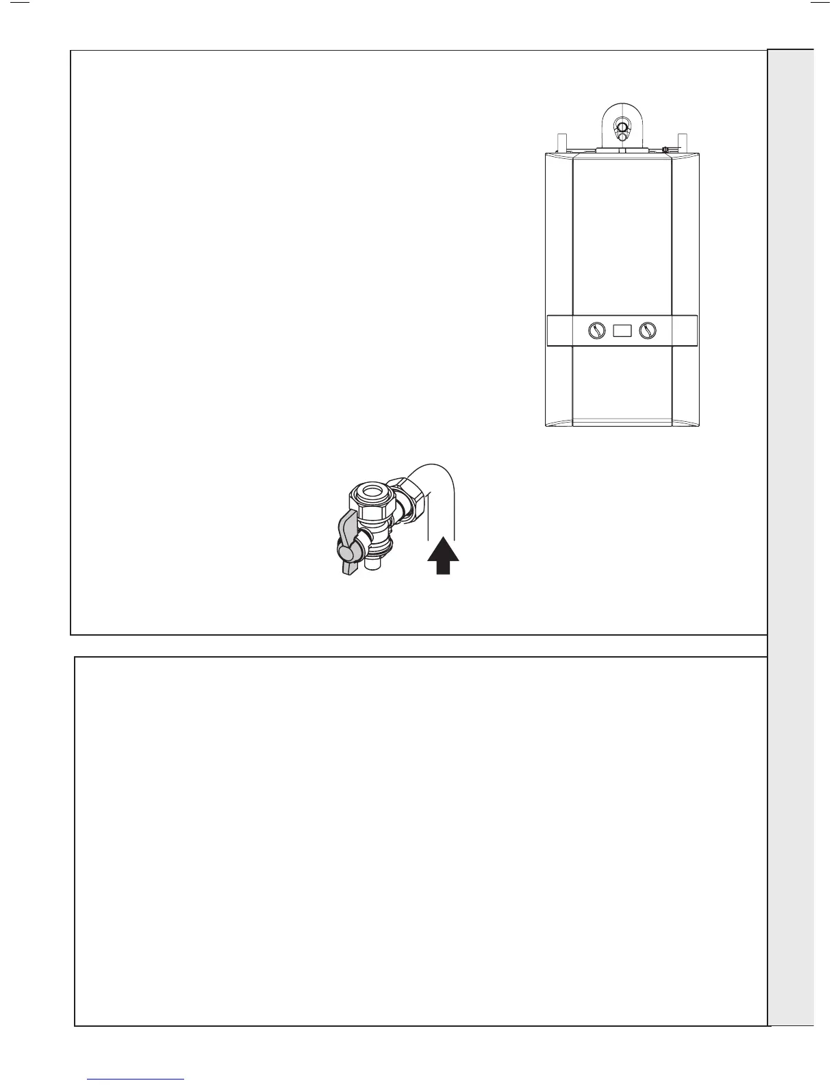
NOTES.
Ensure all pipe blanking plugs are removed before connecting.
Note. The gas isolation handle is
shown in the open position.
WATER CONNECTIONS
The boiler ow and return pipes are supplied tted to the boiler
and ready for top connection.
Note. For heating loads in excess of 17.6kW (60,000 Btu/h)
use 28mm x 22mm connectors to connect the boiler ow and
return pipes to 28mm.
Top Connection
Connect the system pipework to the boiler ow and return
pipes.
An optional stand-off kit is available where system pipework
needs to be taken downwards.
GAS CONNECTION
IMPORTANT. The gas service cock is sealed with a non-
metallic blue bre washer, which must not be overheated when
making capillary connections. Refer to Frame 1 for details of
the position of the gas connection.
For additional gas supply information refer to “Gas Supply”
on page 8.
35
ELECTRICAL CONNECTIONS
Wiring should be 3 core PVC insulated cable, not less than
0.75mm
2
(24 x 0.2mm), and to BS 6500 Table 16. For IE
reference should be made to the current ETCI rules for
electrical installations.
The mains supply to the boiler and system wiring centre shall
be through one common fused double pole isolator. For
heating systems, and where practicable replacement boiler
installations, the isolator shall be situated adjacent to the
appliance.
NOTE. THE APPLIANCE MUST BE WIRED WITH A
PERMANENT LIVE SUPPLY. THE BOILER WARRANTY
WILL BE INVALID IF THIS REQUIREMENT IS NOT
COMPLIED WITH.
WARNING. This appliance MUST be earthed.
A mains supply of 230Vac ~ 50 Hz is required.
The fuse rating should be 3A. All external controls and wiring
must be suitable for mains voltage.
Wiring external to the boiler MUST be in accordance with the
current I.E.E. (BS.7671) Wiring Regulations and any local
regulations.
 Loading...


