33
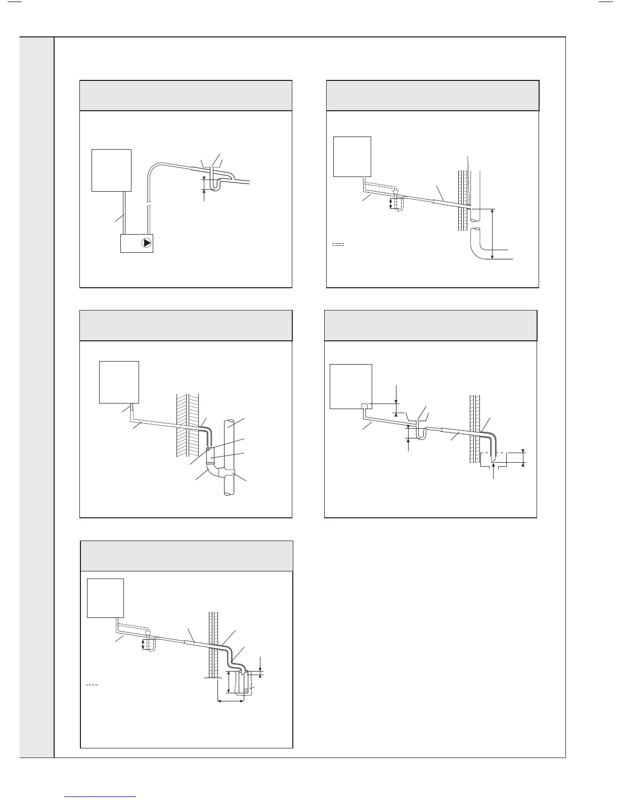
CONDENSATE DRAIN - CONT’D.......
Visible air break
Condensate pump
(Install in accordance with manufacturers instructions)
Min Ø 19mm
Internal pipe
Boiler
with 75mm
sealed
condensate
trap
75
Min Ø 19mm
Internal pipe
Min Ø 30mm
Internal pipe
Air gap
External air
break
combined foul/
rain water drain
Terminated
and cut at 45º
43mm 90º male/
female bend
Water/
weather proof
insulation
68mm Ø PVCU
Strap on fitting
Boiler
with 75mm
sealed
condensate
trap
Boiler
with 75mm
sealed
condensate
trap
Min Ø 19mm
Internal pipe
Min Ø 30mm
Internal pipe
Water/Weather
proof insulation
Max 3m external
pipework
Limestone
chippings
≥ 500
≥ 300
≥ 25
75
Boilers without 75mm sealed
condensate trap must be fitted with
a 75mm trap and visible air break
2 rows of three Ø12mm holes
25mm centres, 50mm from
the bottom of the tube, facing
away from the house
Minimum
connection
height up to 3
storeys
Soil & vent stack
≥ 450
Boiler
with 75mm
sealed
condensate
trap
Min Ø 19mm
Internal pipe
Min Ø 30mm
Internal pipe
Water/weather
proof insulation
75
Boilers without 75mm sealed
condensate trap must be fitted with
a 75mm trap and visible air break
Visible air break
at plug hole
Min Ø 19mm
Internal pipe
Sink, basin, bath or
shower with integral
overflow and 75mm trap
Minimum 30mm
internal pipe
Water/
weather proof
insulation
≥ 25 Below grate
45º pipe
termination
Boiler
with 75mm
sealed
condensate
trap
75
≥ 100
Figure 3 - Connection of a Condensate Pump Typical
Method (see manufacturers detailed instructions)
Figure 4 - Connection of condensate Drainage Pipe to
External Soil & Vent Stack
Figure 5 - Connection of a Condensate Drainage Pipe to an
External Rainwater Downpipe (only combined foul/rainwater
drain)
Figure 7 - Connection of a Condensate Drainage Pipe to an
External Purpose Made Soak Away.
Figure 6 - Connection of Condensate Drainage Pipe
Upstream of a Sink, Basin, Bath or Shower Waste Trap to
External Drain, Gulley or Ranwater Hopper
INSTALLATION
 Loading...


