INTRODUCTION
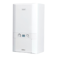
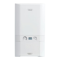
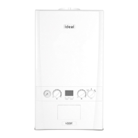
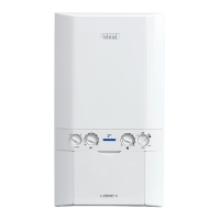
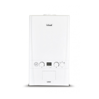
The Logic Heat range of boilers are wall mounted, full sequence,
automatic spark ignition, low water content, fanned ue, high
efciency, condensing, heating only gas boilers.
Note. Due to the high efciency of the boiler a plume of water
vapour will form at the terminal during operation.
Central heating (CH) output is fully modulating with a range of:
12 4.8 to 12kW (16,500 to 41,100 Btu/h)
15 4.8 to 15kW (16,500 to 51,300 Btu/h)
18 4.8 to 18kW (16,500 to 61,600 Btu/h)
24 4.8 to 24.2kW (16,500 to 82,600 Btu/h)
30 6.1 to 30.3kW (20,700 to 103,300 Btu/h)
A variable CH temperature control is tted on the user control.
The boiler includes as standard:
- Boiler frost protection
Notes. The appliance must be wired with a permanent live
supply, or the boiler frost protection will not operate.
The System pump must be wired to the boiler.
The boiler warranty will be invalid if these requirements
are not complied with.
The boiler casing is of white painted mild steel.
The boiler temperature control is visibly located in the control
panel on the front of the boiler.
The heat exchanger is manufactured from cast aluminium.
Note that these boilers cannot be used on systems which include
gravity circulation.
The boiler is suitable for connection to fully pumped open vented
or sealed water systems. Adequate arrangements for completely
draining the system by provision of drain cocks MUST be provided
in the installation pipework.
Pipework from the boiler is routed upwards.
A rear ue outlet kit (55/80) is available which provides a compact
installation.
Data Plate
The boiler model and serial number can be located on the bottom
of the boiler casing, shown in Frame 1 - Water & Gas Connection
Diagram.
OPERATION
When there is a demand for CH, the heating system is supplied at
the selected temperature of between 30
o
C and 80
o
C.
The boiler features a comprehensive diagnostic system which
gives detailed information on the boiler status when operating,
and performance of key components to aid commissioning and
fault nding.
SAFE HANDLING
This boiler may require 2 or more operatives to move it to its
installation site, remove it from its packaging base and during
movement into its installation location. Manoeuvring the boiler
may include the use of a sack truck and involve lifting, pushing and
pulling.
Caution should be exercised during these operations.
Operatives should be knowledgeable in handling techniques when
performing these tasks and the following precautions should be
considered:
• Grip the boiler at the base.
• Be physically capable.
• Use personal protective equipment as appropriate, e.g. gloves,
safety footwear.
During all manoeuvres and handling actions, every attempt should
be made to ensure the following unless unavoidable and/or the
weight is light.
• Keep back straight.
• Avoid twisting at the waist.
• Avoid upper body/top heavy bending.
• Always grip with the palm of the hand.
• Use designated hand holds.
• Keep load as close to the body as possible.
• Always use assistance if required.
OPTIONAL EXTRA KITS
• Horizontal Flue Terminal (600mm long)
• Horizontal Flue Terminal (1000mm long)
• Flue Extension Ducts (1000mm long)
• Flue Extension Ducts (2000mm long)
• Flue Extension Ducts (500mm long)
12 - 24 up to 9m
30 up to 8m
•
• 90
o
Elbow Kit (maximum per installation).
12 - 30 up to 6 elbows
• 45
o
Elbow Kit (maximum per installation).
12 - 30 up to 6 elbows
• Concentric Flue Screw Retaining Kit
• Roof Flue Kit (to a maximum of 7.5m)
• Powered Vertical Flue Kit (5m primary and 17m secondary
is a typical maximum length. For alternative details refer to
Powered Vertical Instructions)
• Weather Collar (Universal)
 Loading...
