325
324
219
303
506
308
307
306
106
512
505
504
215
225
227
233
226
224
503
214
204
211
217
223
218
103
313
105
104
401
302
229
231
301
304
228
203
314
BCC*
206
205
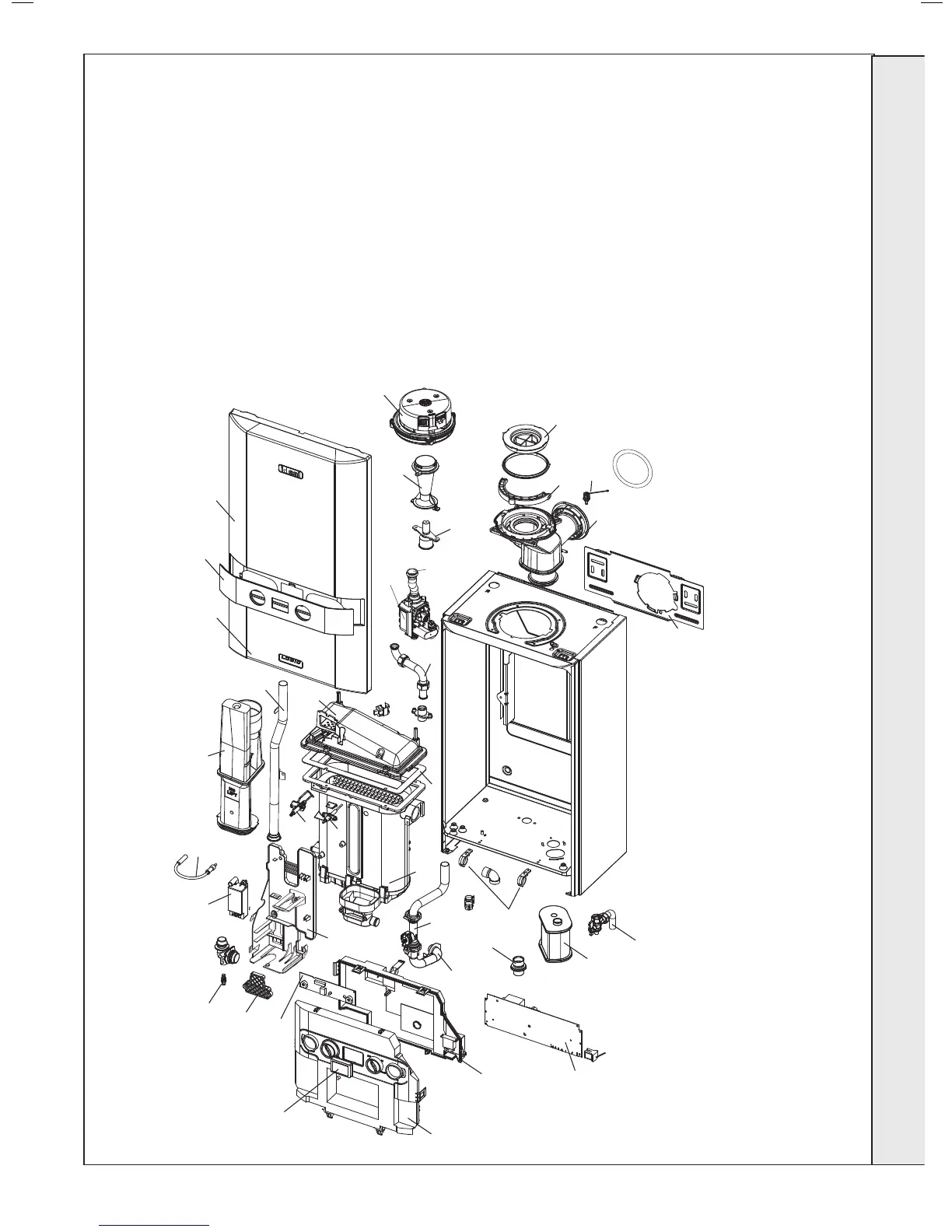
Note that item numbers are linked to the spares list
103 HEAT EXCHANGER DRAIN
104 FLOW SENSOR
105 PIPE - FLOW
106 PIPE - RETURN
203 GAS COCK
204 PIPE - GAS INLET
205 GAS VALVE
206 PIPE - GAS INJECTOR
211 INJECTOR ASSEMBLY
214 VENTURI
215 FAN
217 BURNER
218 GASKET - BURNER
219 SUMP CLEAN OUT COVER
10
BOILER ASSEMBLY - Exploded View
223 FLUE MANIFOLD
224 FLUE MANIFOLD TOP
225 FLUE MANIFOLD - TOP SEALING CAP
226 FLUE MANIFOLD - REAR SEALING CAP
227 CLAMP RETAINING FLUE TURRET
228 HOSE CONDENSATE INTERNAL
229 SIPHON TRAP
231 CONDENSATE OUTLET CONNECTION
233 FLUE SENSING NIPPLE
301 CONTROLS BOX FIXINGS HINGE & SPRING
302 PRIMARY PCB*
303 CUI BOARD
304 CONTROL THERMISTOR (RETURN)
306 ELECTRODE IGNITION
307 ELECTRODE DETECTION
308 IGNITOR UNIT
313 IGNITION LEAD
314 CONTROL BOX LENS
324 CONTROLS BOX LID
325 CONTROL BOX FRONT
401 HEAT ENGINE
503 WALL MOUNTING BRACKET
504 FRONT PANEL
505 FASCIA
506 BRACKET - GAS VALVE
512 INFILL FRONT PANEL
INSTALLATION
* Note that production boiler PCBs are factory pre-set to
operate for boiler range and output, but when ordering
Primary PCB as a spare, an additional Boiler Chip Card
(BCC) MUST also be purchased for your specic boiler
range and output.
 Loading...


