74
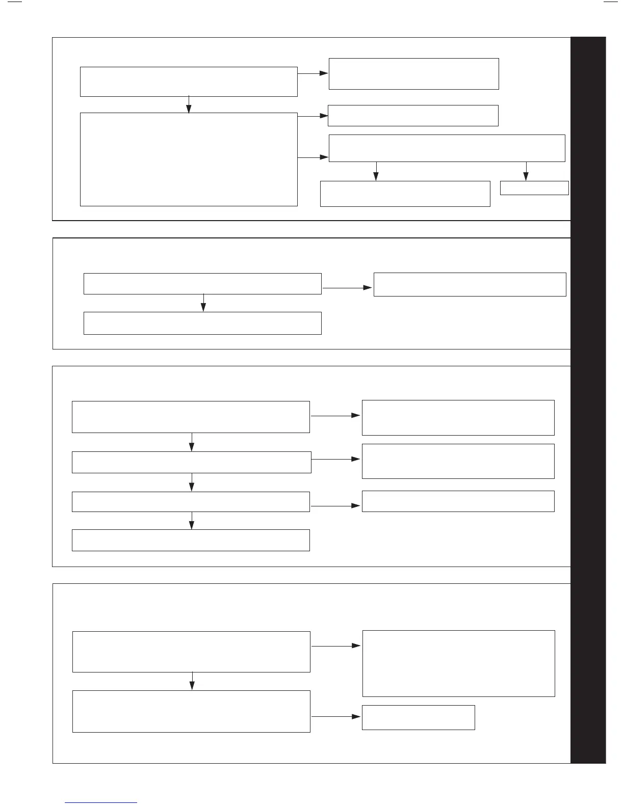
ALTERNATING ‘F’ AND ‘6’ - OUTSIDE SENSOR FAULT
Disconnect the wires to the outside sensor.
Check the resistance using a suitable multimeter
connected across the Outside Sensor’s terminal pins.
At 0
o
C expect 31,000 - 35,000 Ohms
At 15
o
C expect 15,000 - 16,500 Ohms
At 30
o
C expect 7,700 - 8,500 Ohms
Is the Outside Sensor value correct?
NO YES
Is wiring securely connected between the incoming terminal
block boiler connection of the Outside Sensor and PCB?
Replace PCB
Fit a new Outside Sensor
NO
YES
Securely connect the wiring at the
Terminal Block and the PCB
Is the wiring securely connected at both the boiler and
Outside Sensor?
YES
NO
Securely connect the wiring at both the
boiler and Outside Sensor
75
ALTERNATING ‘F
Is the pump connected the correct way?
YES
NO
Reverse pump
Check that the system pipework is correct.
76
ALTERNATING ‘F AND ‘d’ - NO WATER FLOW
Are the boiler and CH system lled with water and all
isolation and radiator valves open?
YES
NO
Fill and vent the system and open all isolation
valves.
Turn power off and on, is the pump rotating?
NO
Check pump and check electrical connection to
pump.
Are connections to water ow sensor secure?
YES
NO
Re-t connector.
YES
Replace water ow sensor.
77
ALTERNATING ‘c’ AND ‘2’ - BCC FAULT (BOILER CHIP CARD)
Is the correct BCC for the boiler securely inserted into the
slot at the front left of the PCB?
(identied by the label on the BCC)
YES
NO
Securely insert the correct BCC for the boiler
into the PCB and after switching power on and
‘c0’ being shown, restart boiler.
Note. Ensure the correct orientation of BCC by
placing “TOP” side up.
Replace the BCC with a new BCC (that is correct for the
boiler). After switching power on and ‘c0’ being shown,
press restart. Is ‘c2’ still shown?
Replace PCB
YES
RESTART PROCEDURE - To restart boiler, turn mode knob to restart position and immediately turn knob back to required setting.
 Loading...


