57
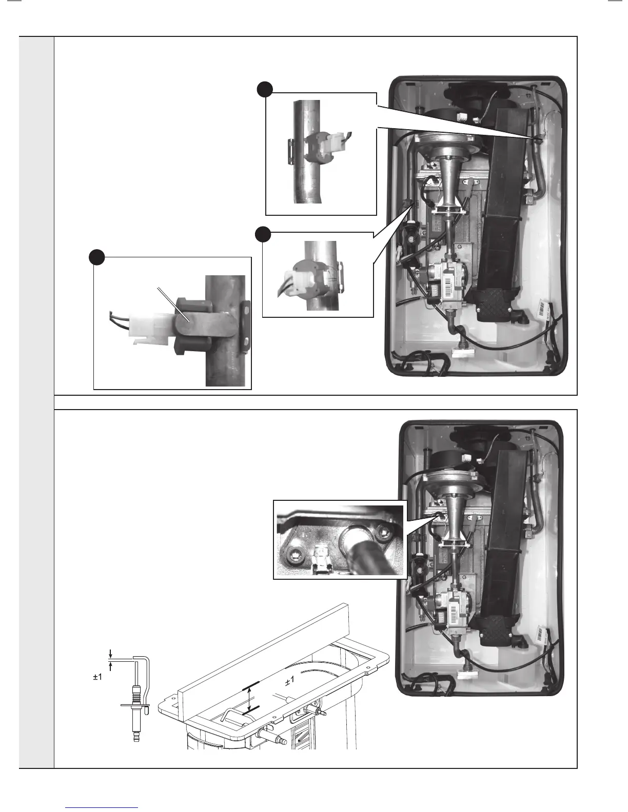
IGNITION ELECTRODE REPLACEMENT
1. Refer to Frame 52.
2. Remove the burner. Refer to Frame 55.
3. Unplug the ignition lead from the electrode.
4. Remove the earth lead from the ignition
electrode.
5. Remove the 2 screws holding the ignition
electrode to the combustion chamber.
6. Remove the electrode.
7. Fit the new ignition electrode, using the
new gasket supplied. Check dimensions as
shown.
8. Reassemble in reverse order.
9. Check the operation of the boiler. Refer to
Frames 41 & 42.
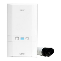
56
CONTROL & RETURN THERMISTOR RENEWAL
1. Refer to Frame 52.
2. Disconnect the electrical leads from the
thermistors.
3. Unclip the ow thermistor from the ow pipe
and withdraw it from the boiler.
4. Unclip the return thermistor from the return
pipe and withdraw it from the boiler.
5. Reconnect the electrical lead to the new
thermistors and reassemble in reverse order,
ensuring that the thermistor is securely tted
to the pipe on the thermistor locator tab as
shown.
6. Check the operation of the boiler. Refer to
Frames 41 & 42.
Ignition Electrode
 Loading...