58
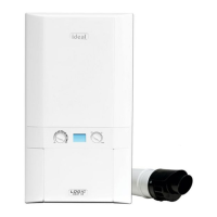
FLAME DETECTION ELECTRODE REPLACEMENT
59
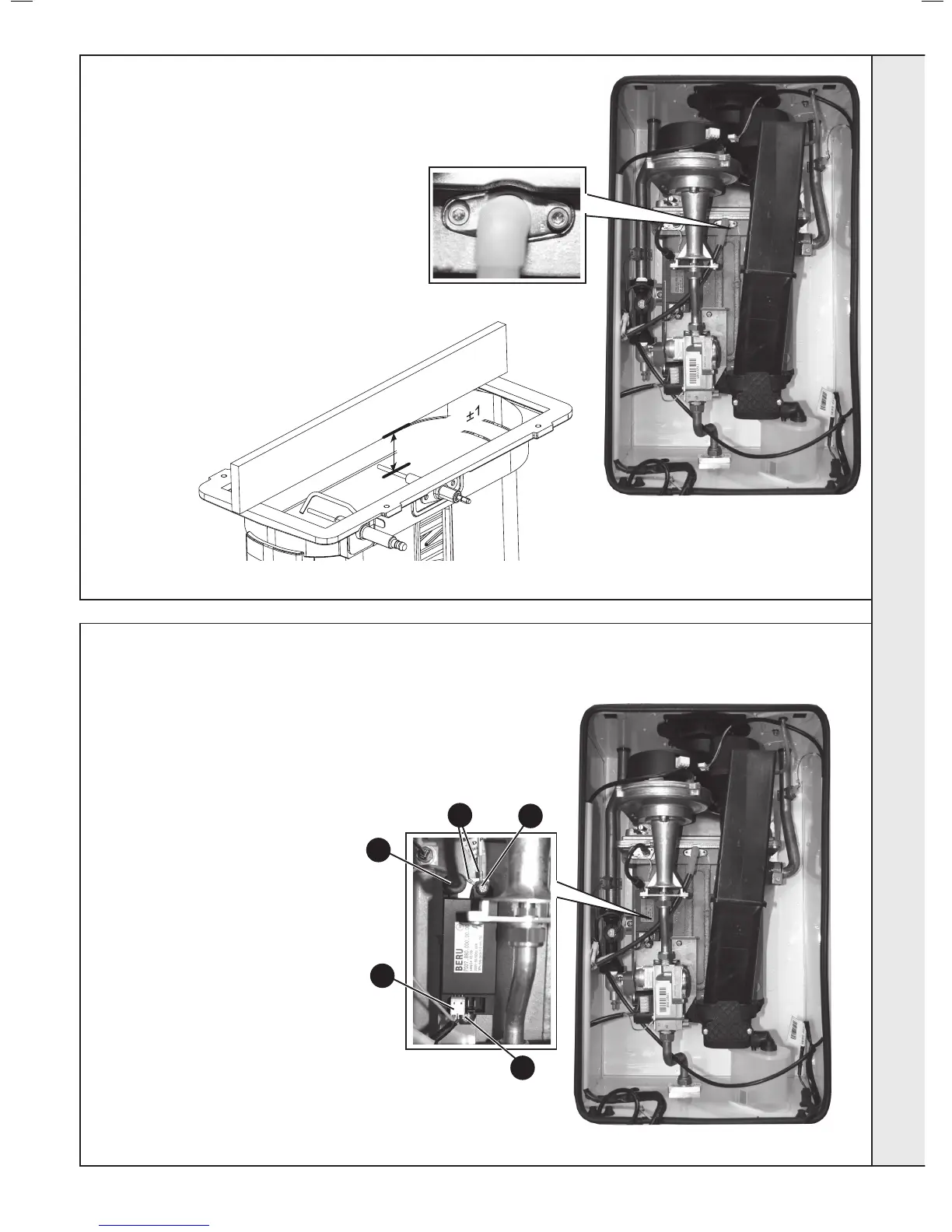
SPARK GENERATOR REPLACEMENT
1. Refer to Frame 52.
2. Disconnect the leads from the spark
generator.
3. Remove the M5 screws securing the
spark generator to the boiler chassis.
4. Fit the new spark generator and re-
assemble in reverse order ensuring
the two earth leads are correctly
replaced.
5. Check operation of the boiler. Refer
to Frames 41 & 42.
Flame Detection Electrode
Spark Generator
1. Refer to Frame 52.
2. Remove the burner. Refer to Frame 55.
3. Unplug the ame detection lead from the
electrode.
4. Remove the 2 screws retaining the detection
electrode.
5. Remove the electrode.
6. Fit the new ame detection electrode (check
dimension as shown below), using the new
gasket supplied.
7. Reassemble in reverse order.
8. Check the operation of the boiler. Refer to
Frames 41 & 42.
3
3
2
2
4
SERVICING
 Loading...