21
Installation and Servicing
Section 2 - Installation
INSTALLATION
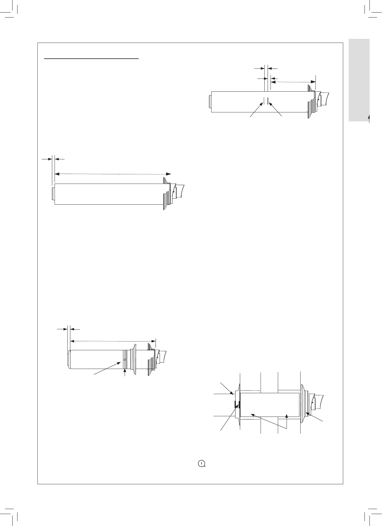
CUTTING HORIZONTAL FLUE TERMINAL
(non-telescopic)
1. Measure the required cut ue length (A + 44 mm)
2. Measure from the outer terminal lip to the end of outer
tube. Mark the required cut length (A + 44 mm) around
the circumference of the outer tube and cut following the
mark to ensure it is cut square.
3. Mark and cut the inner tube 10 mm longer than the outer
tube ensure the cut is square.
4. Remove all burrs on the inner and outer tube and place a
light chamfer on the inner tube to aid with assembly.
SETTING TELESCOPIC FLUE
1. Measure the required length (A + 44 mm)
2. Pull ue apart until the desired length is achieved
ensuring the stop mark is not visible.
3. Ensure both ue seams are at the top and the ue outlet
terminal is uppermost.
4. Drill a 3.5 mm hole through the small and large outer
tube using the pilot hole on the large outer tube.
5. Secure large and small outer tube using the screws
provided.
6. Seal the joint on the out tube with the tape provided.
7. Fit the internal and external wall seals.
FITTING THE FLUE THROUGH THE WALL
(Internal Installation)
1. Measure the thickness of the wall.
2. To this measurement add 14 mm.
3. Make a mark on the ue shown as mark 1 (top right).
4. Make another mark on the ue a further 14 mm in shown
as Mark 2 above right.
5. Fit the external wall seal (black) to the ue terminal
ensuring it is tted on the terminal outer lip seal.
6.
Fit the inner wall seal approximately 65 mm prior to Mark 2.
2.13 CUTTING THE FLUE
7. Place the terminal end of the ue into the 127 mm core
drilled centrally and slowly apply slight pressure and
move the ue up or down or side to side. This will cause
the external wall seal to fold in and allow the ue to pass
through the wall.
8. When the inner wall seal is ush against the wall pull
back the ue until Mark 1 is ush with the inner wall
surface.
9. Hold the ue steady and push the inner wall seal
towards the wall until Mark 2 is just visible.
FITTING THE FLUE THROUGH THE WALL
(External Installation)
1. Follow steps 1 - 5 from above.
2. Push the ue through the 127 mm core drilled hole from
the outside
3. Return inside the property and t the inner wall seal to
the ue.
4. Pull the ue internally until Mark 1 is ush with the inner
wall surface.
5. Holding the ue in this position push the inner wall seal
towards the wall until Mark 2 is just visible.
If Mark 1 is not ush with the inner wall surface and can be
seen prior to the wall surface, then the external wall seal
will have been dislodged and will require to be re-tted. If
this situation occurs, then please start the process from the
beginning.
On completion the ue will be correctly installed as below.
IMPORTANT: Ensure no White ue is visible between
the ue terminal and the wall.
Flue length measured from outer terminal lip
to end of outer ue
A + 44 mm
10 mm
10 mm
Mark Cut Length = “A” + 44 mm from terminal lip
A + 44 mm
+14 mm
Wall Thickness
+14 mm
Mark 2
Mark 1
10 mm
Adjust to Length =
“A” + 44 mm from terminal lip
Drill Hole
Adhere sealing tape
Mark 1 Flush with inter wall
125 mm Cored
drilled hole
Correctly sealed
wall seal
Mark 2 Flush with
the inner wall seal
 Loading...