35
Installation and Servicing
Section 3 - Servicing
3.1 SERVICING SCHEDULE
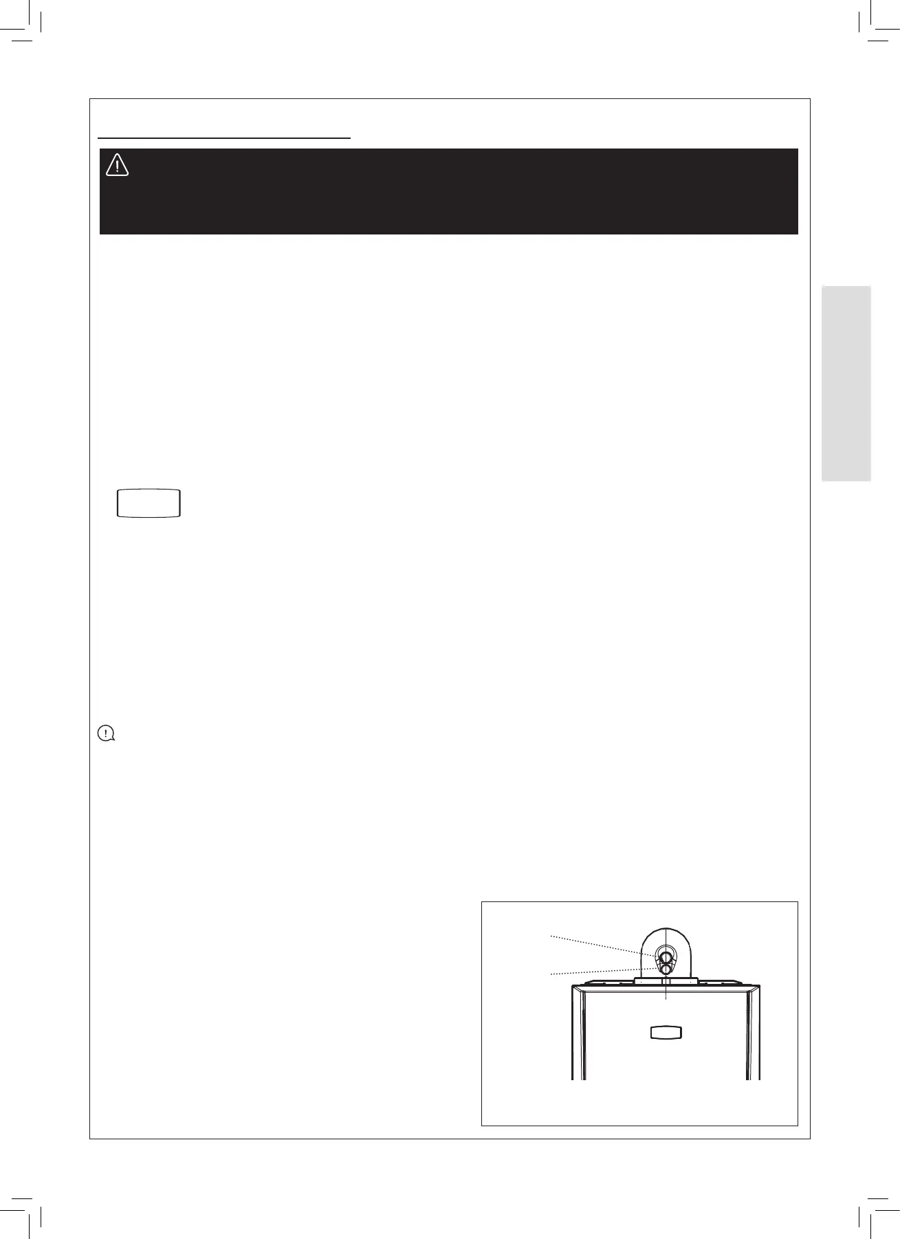
Ensure all caps and seals are re-tted after use
Air Sample
Point
Flue
Sampling
Point
To ensure the continued safe and ecient operation of the appliance it is recommended that it is checked at regular intervals
and serviced as necessary. The frequency of servicing will depend upon the installation condition and usage but should be
carried out at least annually.
For the latest copy of literature, visit our website idealheating.com.
WARNING: Servicing can only be carried out by Gas Safe Registered Engineers
Always turn OFF the gas supply at the gas service cock, and switch OFF and disconnect the electricity supply to the
appliance before servicing
Combustion testing must be carried out by a competent person using a combustion analyser conforming to
BS EN 50379-3:2012.
CLEANING PROCEDURE
1. Remove the casing.
2. Visually check the appliance for signs of leakage.
3. Remove the ue manifold.
4. Remove the fan.
5. Remove the burner.
6. Ret the sump outlet cover.
7. Clean the heat exchanger by pouring warm water across
the whole heat engine to ush deposits taking care to
avoid pouring water over the electrode.
8. Check the electrode for damage and clean using an
abrasive cloth. Check and adjust the spark gap. Replace
the electrode if damaged.
9. Clean out the sump outlet to ensure any debris is
removed.
10. Remove and clean the condensate trap and re- prime the
trap before re-installing.
11. Re-assemble the components in reverse order.
12. Carry out post service checks on the combustion circuit.
See General below.
13. Check the system water quality in accordance with
BS7593:2019.
14. Complete the service record in the Benchmark section.
Do not operate the boiler if the front panel is not tted.
PRELIMINARY INSPECTION
1. Light the boiler and carry out a pre-service check, refer to
the fault nding chart.
2. Check the ue terminal (and terminal guard if tted) for
damage and obstruction.
3. Check combustion by connecting the ue gas analyser to
the ue gas sampling point as shown in the diagram and
measure CO and CO
2
at maximum rate. Set the boiler to
Maximum and Minimum heat inputs.
Refer to Section
3.12
If the CO / CO
2
ratio is greater than 0.004 please proceed
to “Cleaning Procedure”.
If the CO / CO
2
ratio is less than 0.004 please proceed to
“Check Procedure”.
CHECK PROCEDURE
1. Check all water and gas joints for signs of leakage.
Remake any suspect joints ensuring a gas tightness
check is carried out if applicable and the water system is
correctly relled, vented and re-pressurised.
2. Proceed to “IMPORTANT”.
IMPORTANT
1. If, for any reason, the condensate trap has been removed,
ensure the trap is relled with water before re-assembling.
2. After completing the servicing or exchange of components
always ensure all gas valve connections are gas tight with
a gas soundness check up to the gas control valve.
3. When work is complete the front panel MUST be correctly
retted, ensuring that a good seal is made.
4. Complete the service section in the Benchmark
Commissioning Checklist.
GENERAL
During Servicing, and after any maintenance or change of
part of the combustion circuit, the following must be checked:
- The integrity of the ue system and the ue seals.
- The integrity of the boiler combustion circuit and the
relevant seals.
- The operational (working) gas inlet pressure at maximum
rate.
- The gas rate.
- The combustion performance.
 Loading...