45
Installation and Servicing
Section 3 - Servicing
SERVICING
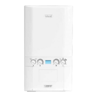
1. Drain the boiler.
2. Remove the expansion vessel.
3. Firstly, increase access area by disconnecting the 22
mm pipe connection at top of pump manifold and bottom
of heat exchanger and remove pipe.
4. The automatic air vent head is retained in the pump body
with a bayonet connection. The air vent head and oat
assembly is removed by turning the head anti-clockwise
(viewed from above) and pulling upwards.
5. Reassemble. Ensure the air vent head ‘o’ ring seal is
tted.
6. Ensure the air vent cap is loose.
7. Rell the boiler. Check for leaks around the new air vent
joint.
Air Vent Cap
Refer to Section
3.24
Refer to Section
2.17
Refer to Section
3.3
Refer to Section
3.2
3.20 PUMP AUTOMATIC AIR VENT REPLACEMENT
Refer to Section
3.2
Refer to Section
3.3
Refer to Section
2.17
3 2
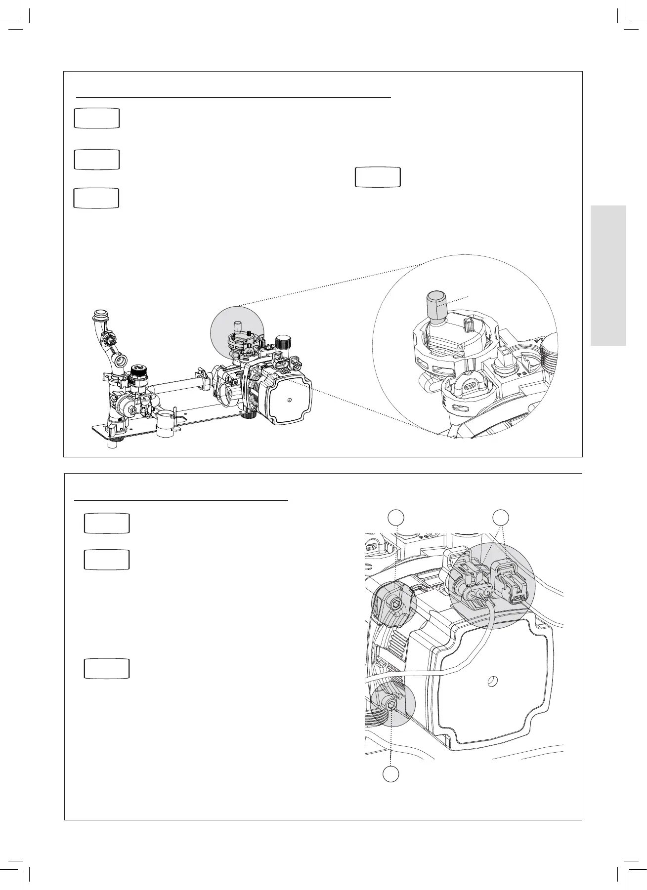
1. Drain the boiler.
2. Disconnect the two electrical leads from the pump.
3. Remove the 4 allen screws retaining the pump head.
4. Remove the pump head.
Be aware of water spillage.
5. Fit the new pump head.
6. Reassemble in reverse order.
7. Rell the boiler.
3.21 PUMP HEAD REPLACEMENT
3
 Loading...