23
Installation and Servicing
Section 2 - Installation
INSTALLATION
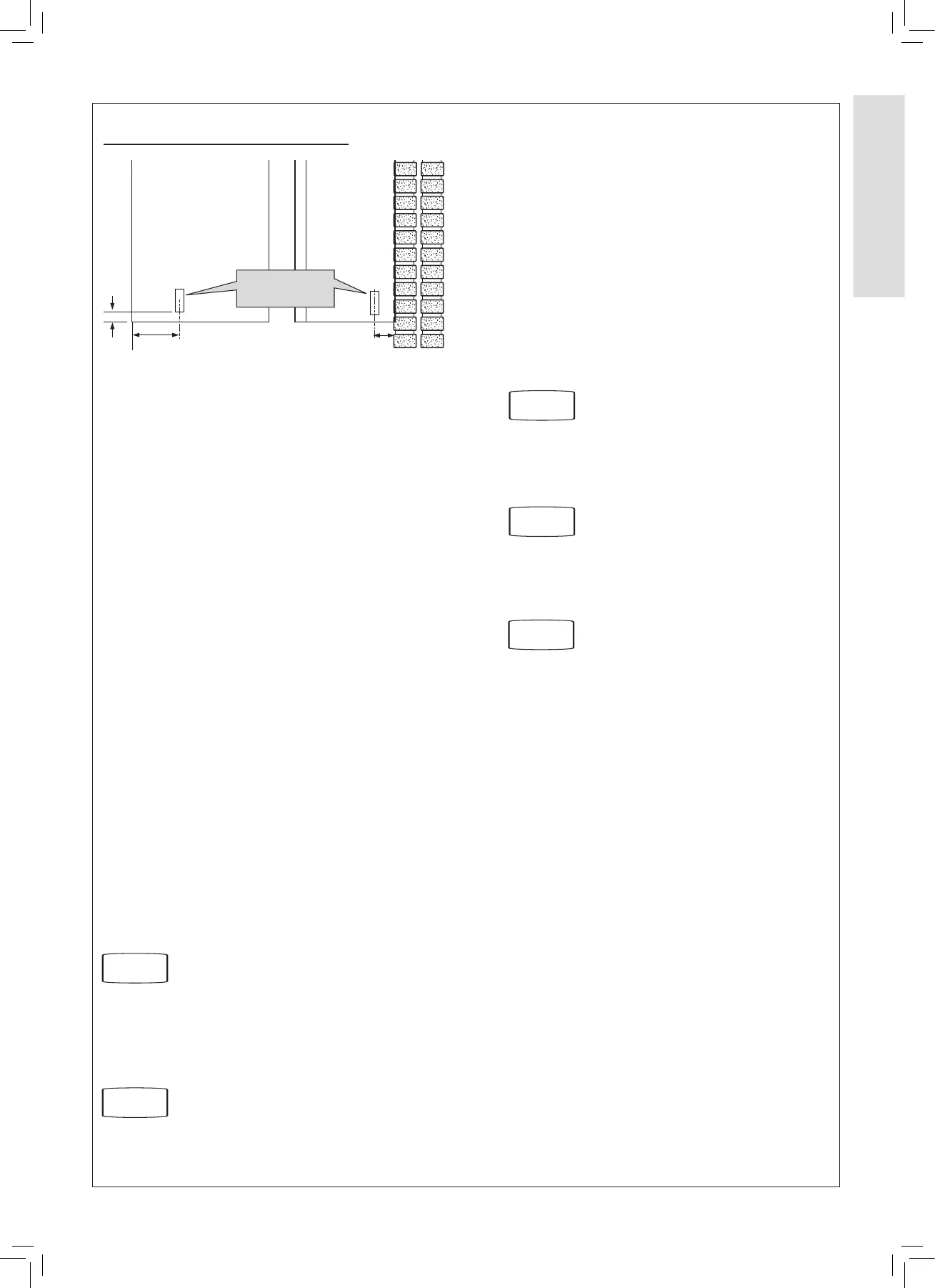
2.15 CONDENSATE DRAIN
This appliance is tted with a siphonic 75 mm condensate trap
system that requires lling before operating the appliance for
the 1st time or after maintenance.
All condensate pipework should conform to the following:
a. Where a new or replacement boiler is being installed,
access to an internal ‘gravity discharge’ termination should
be one of the main factors considered in determining boiler
location.
b. Plastic with push t or solvent connections.
c. Internal plastic pipe work a minimum of 19 mm ID
(typically 22 mm OD).
d. External plastic pipe must be a minimum of 30 mm ID
(typically 32 mm OD) before it passes through the sleeved
wall.
e. All horizontal pipe runs must fall a minimum of 52 mm per
metre away from the Boiler.
f. External & unheated pipework should be kept to a minimum
and insulated with Class “O” waterproof pipe insulation (UV
Resistant).
g. All installations must be carried out in accordance to the
relevant connection methods as shown in the “Condensate
installation diagrams” & BS6798.
h. Pipework must be installed so that it does not allow spillage
into the dwelling in the event of a blockage (through
freezing)
i. All internal burrs should be removed from the pipe work and
any ttings.
In order to minimise the risk of freezing, terminate the
condensate drainage pipe using one of the following methods:
Internal Drain Connections
Route the condensate pipe by gravity to an internal, foul water
discharge point.
Refer to Fig.
1 & 2
Condensate Pump
When it is not practical to terminate the condensate pipe to an
internal foul water discharge point using gravity, use a suitable
pump recommended by the boiler or pump manufacturer.
Refer to Fig.
3
External Drain Connections
The use of an externally run condensate drainage pipe should
only be considered after exhausting all internal termination
options as described previously. An external system must
terminate at a suitable foul water discharge point or purpose
designed soakaway. If an external system is chosen then the
following measures must be adopted:
The external pipe run should be kept to a minimum using the
most direct and “most vertical” route possible to the discharge
point, with no horizontal sections in which condensate might
collect.
- For connections to an external soil/vent stack.Insulation
measures as described should be used.
- When a rainwater downpipe is used, an air break must
be installed between the condensate drainage pipe and
the downpipe to avoid reverse ow of rainwater into the
boiler should the downpipe become ooded or frozen.
- Where the condensate drain pipe terminates in a purpose
designed soakaway (see BS 6798) any above ground
condensate drain pipe sections should be run and insulated
as described above.
- Where the condensate drain pipe terminates over an
open foul drain or gully, the pipe should terminate below
the grating level, but above water level, to minimise “wind
chill” at the open end. The use of a drain cover (as used
to prevent blockage by leaves) may oer further prevention
from wind chill.
Unheated Internal Areas
Internal condensate drain pipes run in unheated areas, e.g. lofts
basements and garages, should be treated as external pipe.
Ensure the customer is aware of the eects created by a frozen
condensate and is shown where this information can be found
in the user manual.
Note. Please check current HHIC condensate discharge
guidance available via the Gas Safe Registered Technical
Bulletins List.
continued . . . . .
Refer to Fig.
4
Refer to Fig.
5
Refer to Fig.
6
 Loading...