B
23
B
23
B
23
B
23
1
2
3
4
1
2
3
20 21
22 23
20
INSTALLER
USER
MAINTENANCE TECHNICIAN
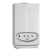
1.18 INSTALLATION OF 80 Ø HORIZONTAL
TERMINALS.
Conguration type B, open chamber and forced draught.
Ø 80 horizontal kit with wall ue exhaust.
Kit assembly (Fig. 20): install the 80 Ø bend (1) with the male
side (smooth) fully home on the central hole of the boiler. Fit the
exhaust terminal (2) with the male end (smooth) to the female end
of the bend (1) up to the stop; making sure that the internal (3)
and external (4) wall sealing plate has been tted. is will ensure
sealing and joining of the elements making up the kit.
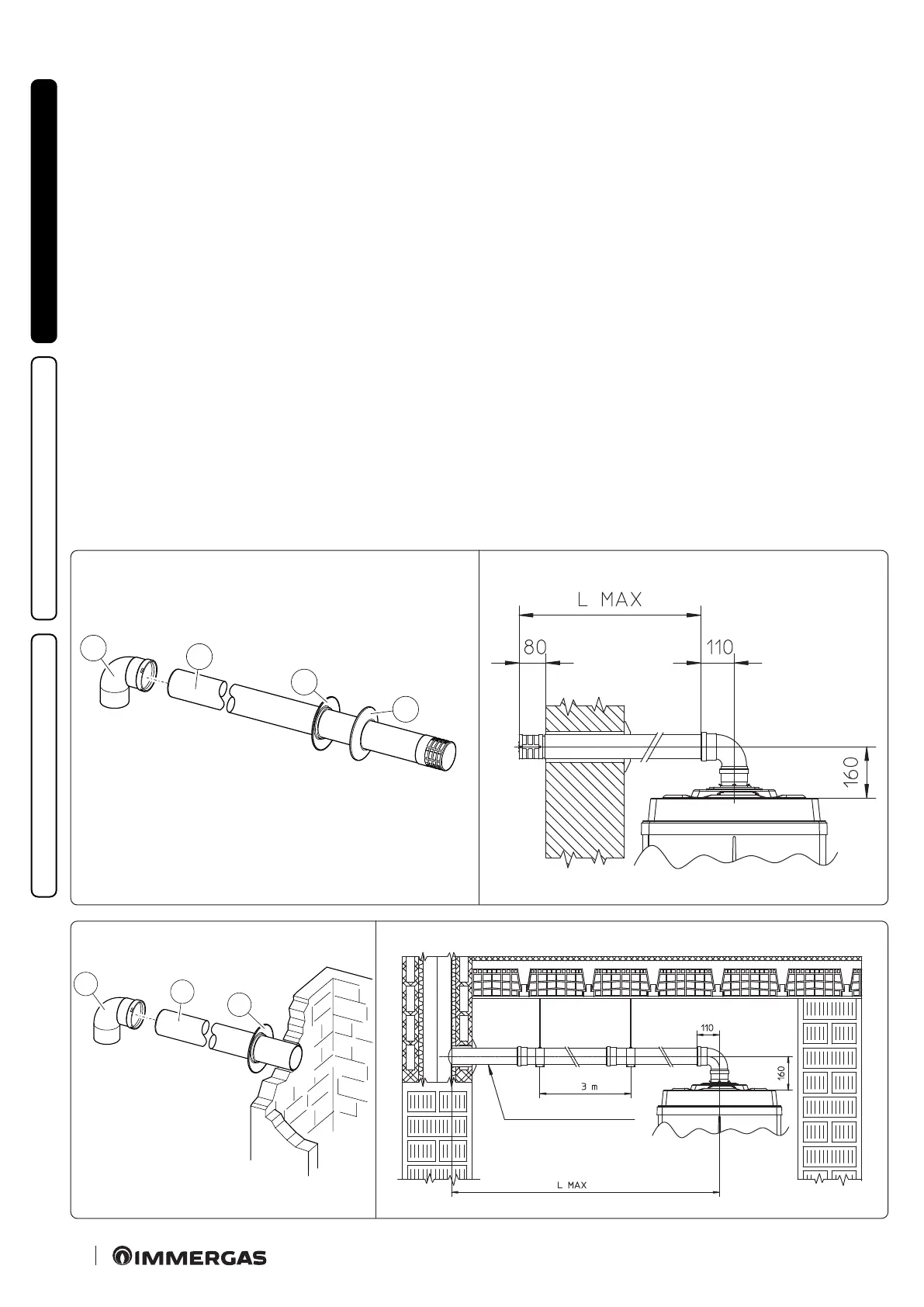
Horizontal kit Ø 80 with exhaust in ue. Kit assembly (Fig. 22):
install the 80 Ø bend (1) with the male side (smooth) fully home
on the central hole of the boiler. Fit the exhaust pipe (2) with
the male end (smooth) to the female end of the bend (1) up to
the stop; making sure that the internal wall sealing plate (3) has
been tted. is will ensure sealing and joining of the elements
making up the kit.
• Maximum length (MAX L) (Fig. 21 and 23). e kit with this
conguration can be extended up to a max. measurement of 28.0
m with Victrix Pro 80 2ErP, 14.0 m with Victrix Pro 100 2ErP
and 8.5 m with Victrix Pro 120 2ErP, including the terminal.
e kit includes:
N° 1 - Bend 90° Ø 80 (1)
N° 1 - 80 Ø exhaust terminal (2)
N° 1 - Internal ring (3)
N° 1 - External ring (4)
e kit includes:
N° 1 - 90° 80 Ø bend (1)
N° 1 - 80 Ø drain pipe (2)
N° 1 - Internal ring (3)
Minimum gradient 1.5 %

 Loading...