2
3
9
INSTALLER
USER
MAINTENANCE TECHNICIAN
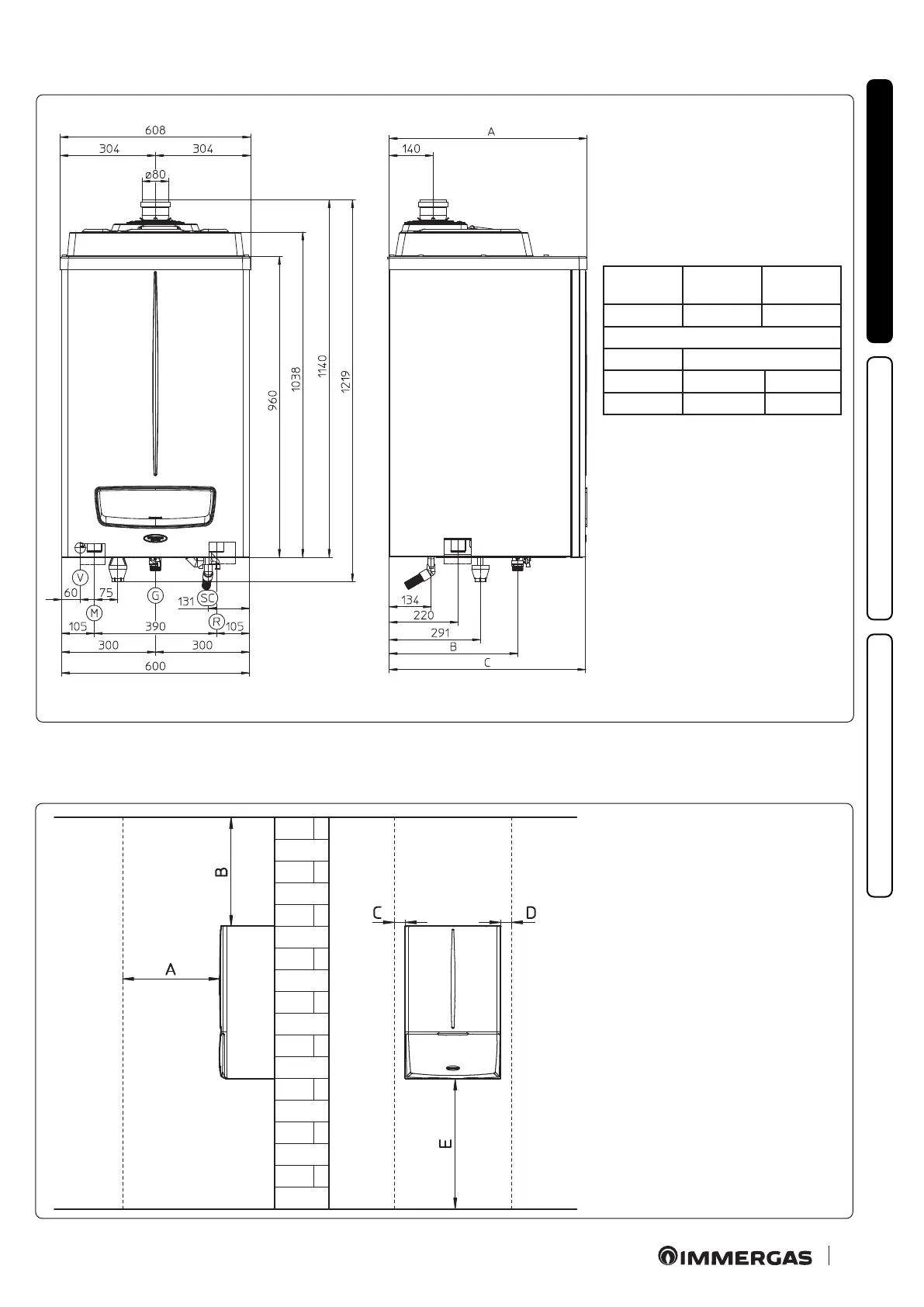
1.2 MAIN DIMENSIONS.
1.3 MINIMUM INSTALLATION DISTANCES.
Key:
A - 450 mm
B - 600 mm
C - 350 mm
D - 350 mm
E - 1000 mm
Height
(mm)
Width
(mm)
Depth
(mm)
1038 600 A
Connections
GAS SYSTEM
G R M
* 1”1/2 1”1/2
Key:
V - Electrical connection
G - Gas supply
R - System return
M - System ow
SC - Condensate drain (minimum
internal diameter Ø 13 mm)
A:
Victrix Pro 80 2ErP = 502 mm
Victrix Pro 100 - 120 2ErP = 632 mm
B:
Victrix Pro 80 2ErP = 265 mm
Victrix Pro 100 - 120 2ErP = 410 mm
C:
Victrix Pro 80 2ErP = 497 mm
Victrix Pro 100 - 120 2ErP = 627 mm
*:
Victrix Pro 80 2ErP = 3/4”
Victrix Pro 100 - 120 2ErP = 1”