27
26
INSTALLER
USER
MAINTENANCE TECHNICIAN
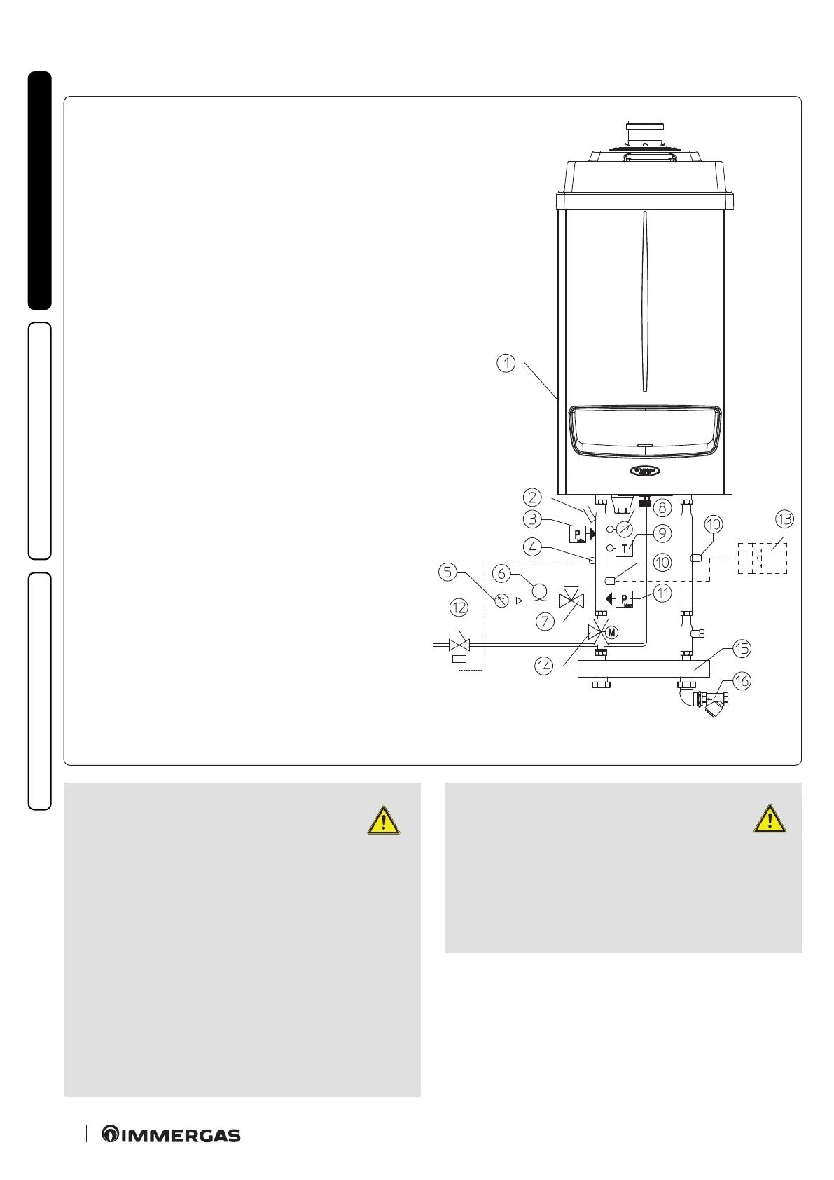
1.28 HYDRAULIC DIAGRAM WITH OPTIONAL.
Key:
1 - Generator
2 - Manometer pocket
3 - Minimum pressure switch
4 - Probe for fuel shut-o valve bulb
5 - Manometer
6 - Damper coil
7 - Manometer-holder cock
8 - ermometer
9 - Manual rearm thermostat
10 - Attachment for expansion vessel
11 - Manual rearm pressure switch
12 - Fuel shut-o valve
13 - Expansion vessel
14 - Boiler connection 3-way valve
15 - Hydraulic manifold/mixer
16 - Slurry collection brass lter
ATTENTION:
the sensitive elements of the automatic
regulation and block circuit breaker
switches and of the thermometer (not
supplied as standard with the boiler) must
be set-up as described in the installation in-
structions in compliance with the provisions
of the "R" collection. Whenever the generators
are not installed in cascade according to the
instructions and the Immergas original kits,
the sensitive elements must be installed on
the ow piping to the central heating system,
immersed in the current of water at not more
than 0.5 metres from the boiler outlet.
The boilers must be installed in the
congurations and with their own ori-
ginal Immergas cascade and safety kits.
e manufacturer
declines all liability
whenever the installer does not use the devices
and Immergas original kits or uses them im-
properly.