1 Concept
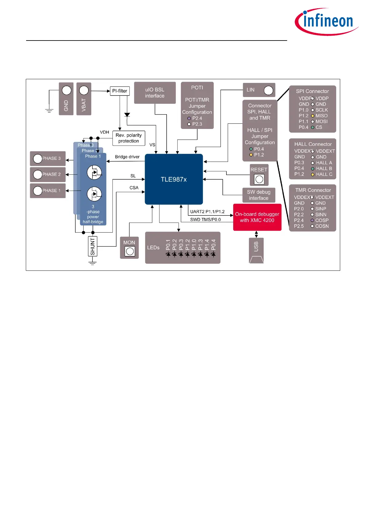
Figure 1 Board concept
This board is designed to provide a simple, easy-to-use tool for getting familiar with Infineon's Embedded
Power IC TLE987x devices. A socket provides the possibility to test and evaluate all ICs of the TLE987x family.
Every pin of the IC is connectable via rows of pin headers. The board is protected against reverse polarity of the
input voltage supply.
Three MOSFET half bridges are placed on the board to drive a BLDC motor. The board is ready to be connected
to a car supply or similar and oers an USB port to use the on-board SWD debugger.
The evaluation board can be operated by standard laboratory equipment, since the power supply and LIN
communication are connected using via banana jacks.
A LED indicates that the board is connected correctly to the power supply. The integrated reverse polarity
protection secures the board from damage by cross connection.
TLE987x EvalBoard
1 Concept
User Manual 5 v1.0
2020-07-30

 Loading...

