4 Jumper settings
LEDs & PINs
JP5
JP2
ILoadVS
ILoadVSD
VDDEXT_LED
JP3
SINN SINP
P0.4
P1.2
POTI
SUPPLY
POTI
SIGNAL
Debugger
Jumper
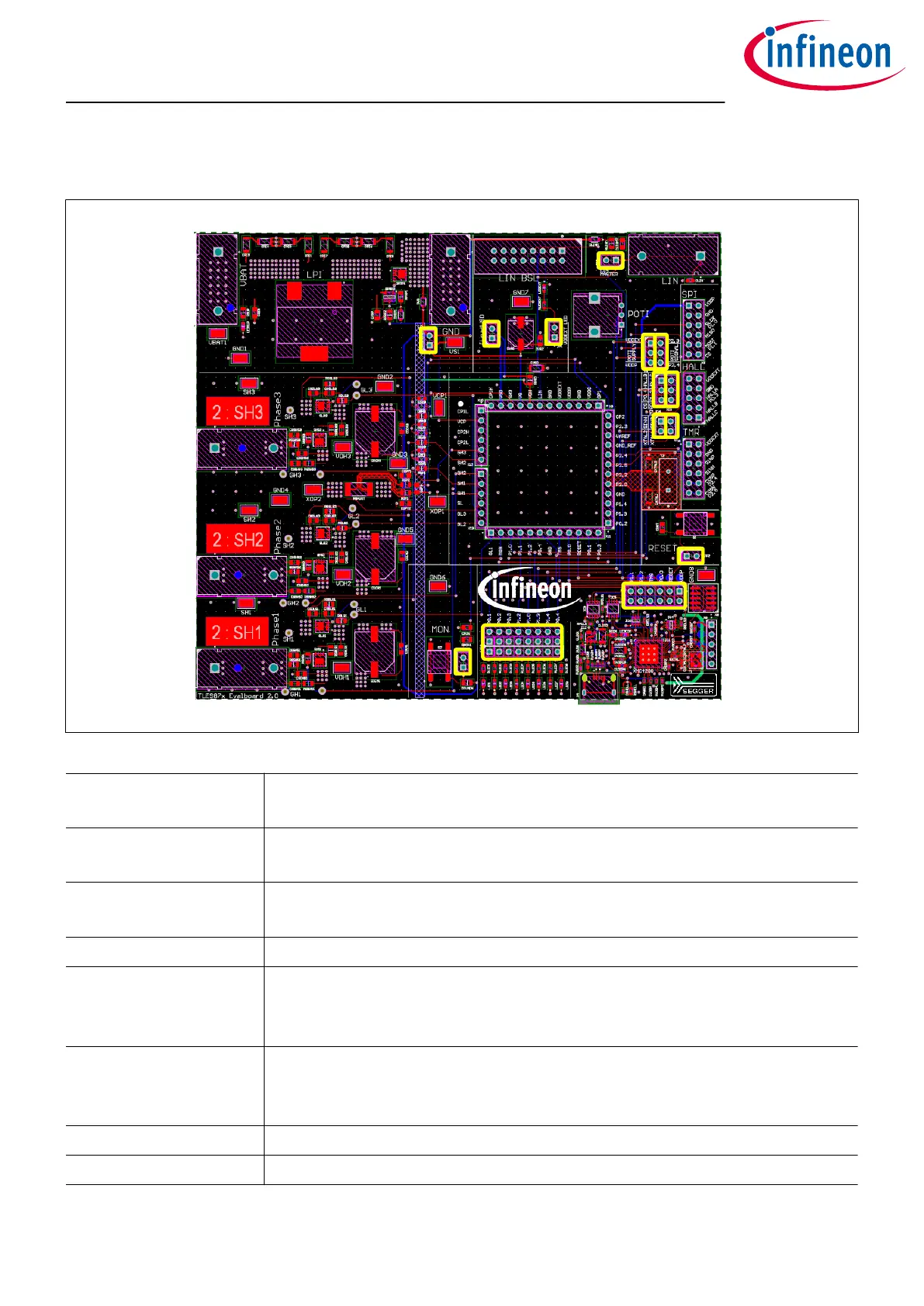
Figure 9 Jumpers
JP2
Set this jumper to connect RESET button to RESET pin.
Open it to disconnect RESET button from RESET pin.
JP3 Set this jumper to terminate TLE987x in daughter board as LIN master.
Open it to terminate TLE987x in daughter board as LIN slave.
JP5 Set this jumper to connect MON button to MON pin.
Open it to disconnect MON button from MON pin.
VDDEXT_LED Set this jumper to enable LED operation at VDDEXT.
ILoadVS This jumper is closed by default.
If this jumper is le open the device is not supplied.
Target is to measure the current flowing into the TLE987x device.
ILoadVSD This jumper is closed by default.
If this jumper is le open the charge-pump is not supplied.
Target is to measure the charge-pump current consumption.
SINN/P Set to use TMR sensor interface.
Debugger Jumper Open debugger jumper to use o-board SWD debugger.
TLE987x EvalBoard
4 Jumper settings
User Manual 10 v1.0
2020-07-30

 Loading...

