22204911 Rev. E EN-11
EN
Disconnect wire from engine spark plug and release
air pressure from the tank before performing
maintenance.
NOTICE
All compressed air systems contain maintenance
parts (e.g. lubricating oil, lters, seperators) which are
periodically replaced. These used parts may be, or may
contain, substances that are regulated and must be
disposed of in accordance with local, state, and federal
laws and regulations.
NOTICE
Take note of the positions and locations of parts
during disassembly to make reassembly easier. The
assembly sequences and parts illustrated may dier
for your particular unit.
NOTICE
Follow engine owner’s manual for engine maintenance
schedules and procedures.
NOTICE
Any service operations not included in this section
should be performed by an authorized service
representatives.
PERIOD MAINTENANCE
Daily or before
each operation
Check lubricant level. Fill as needed.
Drain reciever tank condensate. Open
the manual drain valve and collect,
dispose condensate accordingly.
Check for unusual noise and vibration.
Ensure beltguards and covers are
securely placed.
Ensure area around compressor is free
from rags, tools, debris, and ammable
or explosive materials.
Weekly/
Monthly
Inspect air lter element. Clean/Replace
if necessary.
Inspect for air leaks. Squirt soapy water
around joints during compressor
operation and watch for bubbles.
Check tightness of screws and bolts.
Tighten as needed.
3/500*
12/2000*
Clean exterior.
Change petroleum lubricant while
crankcase is warm.
Change synthetic lubricant while
crankcase is warm.
Replace lter element.
* - indicates months/operating hours, whichever occurs rst
FILTER REPLACEMENT (SS3)
1. Unscrew and remove the wing-nut (A).
2. Remove the lter cover (B), bae (C) and element (D)
from the base (E).
3. Install a new element and reassemble the lter assembly.
NOTICE
The air intake holes in the bae and cover must be
staggered 180°. When reinstalling the assembly at the
inlet connection, ensure the intake hole in the cover is
on the bottom to minimize the entry of foreign matter
from the air.
B
C
D
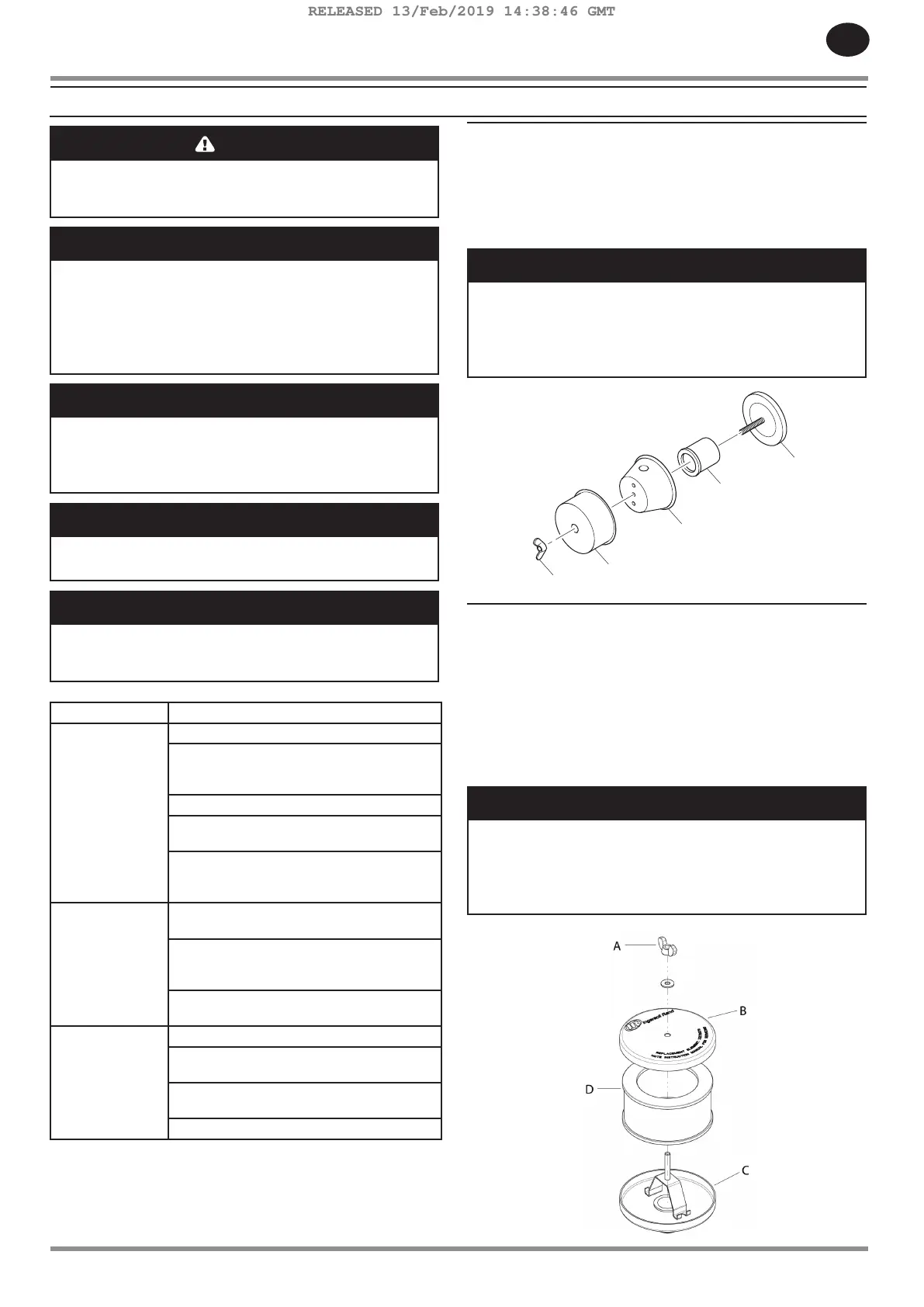
FILTER REPLACEMENT (SS5)
1. Unscrew and remove the wing nut (A) securing the lter
housing (B) to its base (C).
2. Remove the lter busing and withdraw the old lter
element (D) Clean the element with a jet of air or
vacuum.
3. Replace the lter element and housing, securing it in
place with the wing nut previously removed.
NOTICE
The air intake holes in the bae and cover must be
staggered 180°. When reinstalling the assembly at the
inlet connection, ensure the intake hole in the cover is
on the bottom to minimize the entry of foreign matter
from the air.
MAINTENANCE
RELEASED 13/Feb/2019 14:38:46 GMT
 Loading...