2 Installation
- 11 -
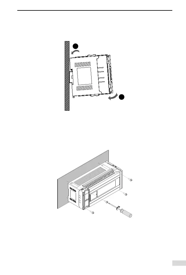
3) Press the PLC in the direction B shown in the following gure until
you hear the click sound. Check if the PLC is fully and vertically
clipped in on the DIN rail.
2.3.2 Mounting on Wall
Use M4 screws to x the PLC on the installation surface in the control
cabinet through the mounting holes on four corners as shown in the
following gure:
2.4 Installation of Expansion Modules
Pull the lock catch on the expansion module to the direction shown in
the following gure. Push the expansion module to the PLC. Pull the
lock catch back to lock it.
 Loading...