3 Wiring
- 16 -
Function Terminals Remarks
Normal
transistor
zero-
clearing NPN
output
CLRx+ and CLRx- (common
terminal) on H
3U
-0808PMRTA
Open-collector, optical coupling
isolated.
Circuit power voltage: 5 to 24 VDC.
Max. output current: Resistive
load: 0.1 A ;
Normal
input
X10-X17 on H
3U
-1616MR/T
X10-X27 on H
3U
-2416MR/T
X10-X43 on H
3U
-3624MR/T
X10-X37 on H
3U
-3232MR/T
STOPx, LSPx, LSNx, DOGx and
STARTx on H
3U
-0808PMRTA
Detection voltage: 24 VDC1
Input resistance: 4.3 kΩ
Hi-speed
input
X00-X07 on H
3U
-1616MR/T
X00-X07 on H
3U
-2416MR/T
X00-X07 on H
3U
-3624MR/T
X00-X07 on H
3U
-3232MR/T
Detection voltage: 24 VDC1
Input resistance: 3.3 kΩ
Max. frequency: 200 kHz
Hi-speed
dierential
input
(Ax+, Ax-) and (Bx+, Bx-) on H
3U
-
0808PMRTA, (PGx+, PGx-) can
serve as the leakage-type and
source-type input terminal.
Input mode: Dierential input,
leakage/source type;
Detection voltage: When the
voltage is larger than 3V, it is ON;
when the voltage is smaller than 2
V, it is OFF.
15 V-24 V is ON. Voltage smaller than 5 V is OFF. The
maximum value is 30 V. When all inputs are ON, the
input voltage should not exceed 26.4 V.
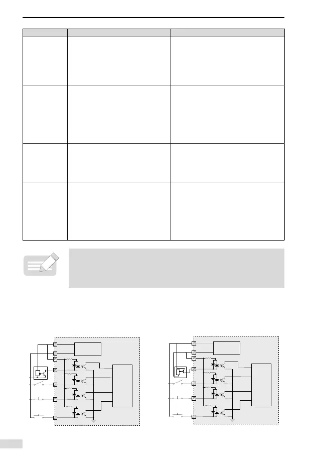
3.2 Input Wiring
3.2.1 Normal Input Wiring
24 VDC output
Logic processing unit
24V+
24V-
24V
0V
X0
X1
X2
Xn
Sensor
User signal wiring
Equivalent circuit in
PLC main module
Various signal input devices
S/S
24 VDC output
Logic processing unit
24V+
24V-
24V
0V
X0
X1
X2
Xn
Sensor
User signal wiring
Equivalent circuit in
PLC main module
Various signal input devices
S/S
Sink input wiring Source input wiring
 Loading...