2 Mechanical Installation and Wiring
- 15 -
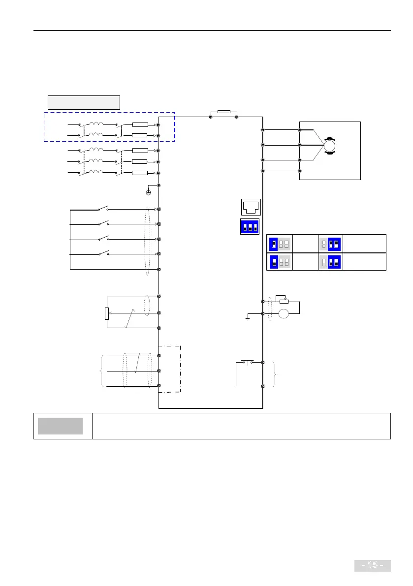
2.2 Wiring
2.2.1 Typical System Connection
■
MD200XXX wiring diagram
U
V
W
DI1
DI2
DI3
DI4
COM
+10V
GND
485+
485-
GND
AI
T/C
T/A
AO
GND
+
BR
Forward run
F4-00 = 1
Forward jog F4-01 = 4
Fault reset F4-02 = 9
F4-03 = 12
1 to 5 kΩ
0 to 10 V or
0 to 20 mA
Modbus-RTU
(
max.: 115200 bps
)
Fd group
External operating panel
(keypad & display)
Analog Voltage
Output: 0 to 10V
Relay output
Normally-open contact
Load: 3 A/250 AC, 3 A/30 VDC
Fuse
Breaker
PE
PE PE
Multi-Reference 1
DI4 supports 20 kHz pulse input.
Default value
1: OFF, 2: OFF, 3: OFF
ON
1
2
3
ON
1 2
3
ON
1 2
3
ON
1 2
3
ON
1 2
3
Current
input
Voltage
input
RS485 termination
resistor connected
RS485 termination
resistor not
connected
MD200
Voltage or current input
selected via DIP switch
(voltage input by default)
F5-02
L1
L2
Single-phase
input
Note: The wiring in dotted line
frame is for single-phase drive
DI terminals are active at a low level and the activation level is lower than 5 V. Their input resistance is 3.6 kΩ,
DI1 to DI3 satises 100 Hz frequency input, and DI4 satises 20 kHz frequency input. The requirement of pulse
duty cycle is 30% to 70%.