2 Mechanical Installation and Wiring
- 16 -
■
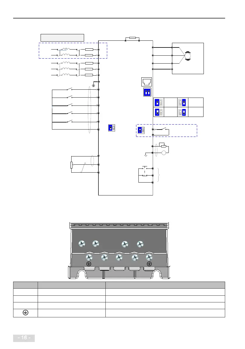
MD200XXX-NC wiring diagram
U
V
W
DI1
DI2
DI3
DI4
COM
+10V
GND
AI
+
BR
Forward run
F4-00 = 1
Forward jog
F4-01 = 4
Fault reset
F4-02 = 9
F4-03 = 12
1 to 5 kΩ
0 to 10 V
External operating panel
PE PE
Multi-Reference 1
DIP Switch
Default value
1: ON, 2: ON
MD200
F4-04 = 0
DIO terminal input
function selection
(DIP switch1select ON)
DIO
ON
1 2
ON
1 2
ON
1 2
3
ON
1 2
DIO functions
as DI
DIO functions
as DO
DI 0V active
DI 24V active
ON
1
2
T/C
T/A
F5-02
Relay output
TA-TB:Normally close
TA-TC:Normally open
Load:3A/250AC 3A/30VDC
T/B
L1
L2
Single-phase
input
Note: The wiring in dotted line frame
is for the single-phase drive.
T
Three-phase
input
F5-04 = 0
COM
DIO
AM
DIO output terminal
function selection
(DIP switch select
OFF)
Analog voltage
output (0 ~ 10 V)
Select DIO
input/output function
via DIP switch
1 2
ON
2.2.2 Terminal Description
■
Terminals of Main Circuit
Terminal Terminal Name Description
L1, L2 Single-phase supply input Connect to the single-phase AC power supply.
BR, (+) Braking resistor connection Connected to an external braking resistor.
U, V, W Output terminals Connect to a three-phase motor.
Ground (PE) Grounding connection.
 Loading...
