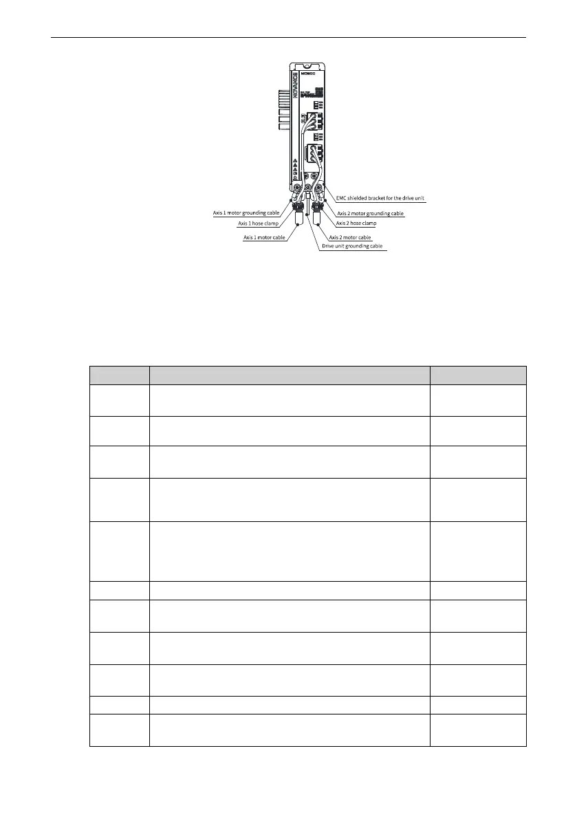
Installation and Wiring
‑31‑
3.2.4 Inspection After Wiring
After wiring has been completed, check the items in the following table. Sign the
corresponding "Applicable?" column after each inspection.
Table 3–1 Wiring checklist
No.
Inspection Item
Applicable?
1
The power input cables are connected to the R/L1, S, and
T/L2 terminals.
2
The motor input cables are connected to the U, V, and W
terminals.
3
The cross‑sectional area of the main circuit cables meets
the requirements.
4
The heat‑shrink tubes have been added to the cores of
main circuit cables, and the tubes completely cover the
cable conductors.
5
Confirm whether the motor output cables are longer
than 150 m (unshielded) or 50 m (shielded). If yes, reduce
the carrier frequency (F0‑15) and add an output reactor
(see the requirements for options).
6
The grounding cables are connected correctly.
7
The AC drive output terminals and control signal
terminals are securely connected.
8
The braking resistor and braking unit (if used) are
connected correctly and have proper resistance.
9
The control circuit cables are shielded twisted pairs
(STPs).
10
The optional cards are connected correctly.
11
If the AC drive is an STO model, confirm that the external
24 V power supply is connected properly.

 Loading...


