- 62 -
3 System Functions
3
Related Parameters
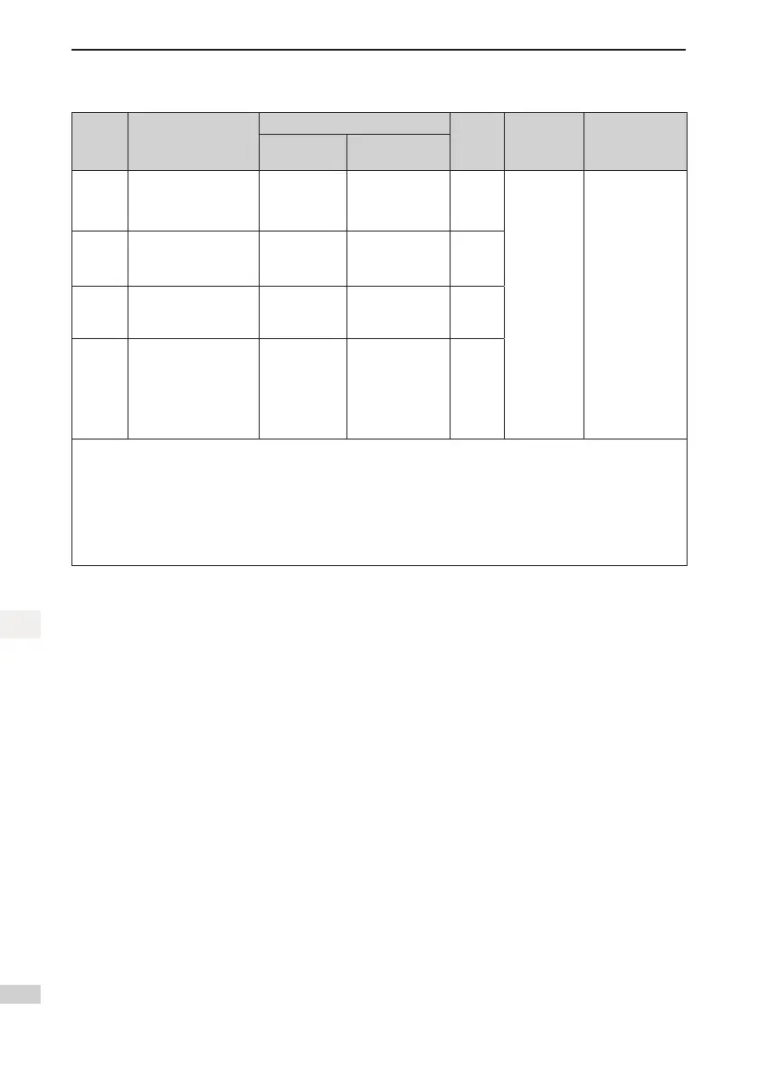
Type Door Control Mode
Parameter Setting
Service
Floor
HCB
Address
Setting
Operation Box
CCB Wiring
Mode
Selection
Other
Parameters
Mode 1 Simultaneous control FC-04 = 0
Fb-00 = 2,
F8-16 = N
(N > F6-00)
20
HCB
address of
front door:
1–20
HCB
address of
back door: N
to N+20
The CCB of front
door is connected
to CN7 on the
CTB.
The CCB of back
door is connected
to CN8 on the
CTB.
Mode 2
Hall call independent,
car call simultaneous
FC-04 = 1 Same as mode 1 20
Mode 3
Hall call independent,
car call manual control
FC-04 = 2
F6-40 Bit4 = 1
Same as mode 1 20
Mode 4
Hall call independent,
car call independent
FC-04 = 3 Same as mode 1 20
In mode 3, the car door to open is controlled as follows:
• Control by button
Connect the button to JP16 on the CCB, and set F6-40 Bit2 to 1.When the button indicator is steady ON, only
the front door opens; when the button indicator is steady OFF, only the back door opens
• Control by switch
Connect the switch to JP20 on the CCB, and set F6-40 Bit15 to 1. When JP20 is ON, only the front door opens;
when JP20 is OFF, only the back door opens.

 Loading...